xp141-241-341-5.0E.pdf - 第10页
C C h h a a p p t t e e r r 1 1 I I n n i i t t i i a a l l A A d d j j u u s s t t m m e e n n t t

FK-9F98-29 XP Series Training Text for Service Engineers
Edition 5.0 XP141E Contents
Fuji Machine Mfg. Co., Ltd. Okazaki.
SMT Equipment Quality Assurance Dept.
CS Section
Chapter 6 Proper Data Measurements
Section No. .................................................................................................... Page No.
6.1 Prism adjustment....................................................................................... 6-1
6.2 Parts camera adjustment........................................................................... 6-2
6.3 Parts camera focus adjustment................................................................. 6-4
6.5 Parts camera resolution............................................................................. 6-5
6.6 Adjusting the mark camera........................................................................ 6-8
6.7 Measuring the mark camera resolution..................................................... 6-9
6.8 Measuring the mark camera orientation.................................................... 6-11
6.9 Measuring the board origin........................................................................ 6-12
6.10 Measuring Z0 ............................................................................................. 6-12
6.11 Measuring the maximum nozzle height..................................................... 6-13
6.12 Reset cylinder............................................................................................ 6-15
6.13 Measuring the R axis offset....................................................................... 6-16
6.14 Measuring the Q-axis offset....................................................................... 6-17
6.15 Measuring the MFU pickup position.......................................................... 6-18
6.16 Pickup height measurement...................................................................... 6-18
6.17 Adjusting the feeder indexing.................................................................... 6-20
6.18 X and Y axis retract position...................................................................... 6-22
6.19 Measuring the parts reject position............................................................ 6-22
6.20 Measuring the parts gage pickup positions............................................... 6-22
6.21 Measuring the matrix data......................................................................... 6-23
6.22 Adjusting the conveyor automatic width changer...................................... 6-24
Chapter 7 Operation and Accuracy
Section No...................................................................................................... Page No.
7.1 Checking idle operation.............................................................................. 7-1
7.2 Placing accuracy measurement................................................................. 7-1
Supplemental Information
XP141E Servo Amp Parameter List
V1.40 Proper Data List
Jig Catalogue
Mechanical Stopper Locations
Servo Amp Battery Replacement Procedure
VME Rack Configuration

C
C
h
h
a
a
p
p
t
t
e
e
r
r
1
1
I
I
n
n
i
i
t
t
i
i
a
a
l
l
A
A
d
d
j
j
u
u
s
s
t
t
m
m
e
e
n
n
t
t
FK-9F98-29 XP Series Training Text for Service Engineers
Edition 5.0 XP141 – Chapter 1 Initial Adjustment Page 1 of 6
Fuji Machine Mfg. Co., Ltd.Okazaki
SMT Equipment Quality Assurance Dept.
1 – 1 CS Section
Chapter – 1 Initial Adjustment
1.1 Leveling
1. Place two track levels at position A, shown in the following diagram:
2. Carry out initial leveling at points 1,2,3,4, then lock all 8 leveling sheets.
3. Leveling tolerance is 0.10mm/1000mm.
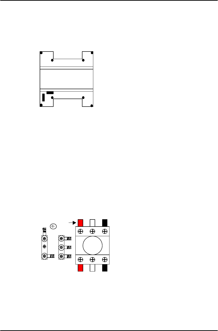
1.2 Power and Air connection
Power supply connection
1. Open the power supply BOX at the lower right hand
side of the machine and pull the power line from the
bottom of the BOX.
2. Connect the ground terminal and the ground wire first.
3. Connect the three wires of the power supply cable to the three breaker box (KG41B)
terminals.
L1: red L2: white L3: black
A
1
23
4
L1 L2 L3
Red