xp141-241-341-5.0E.pdf - 第119页
FK-9F98- 29 XP Series Training Text for Service Engineers Edition 5.0 XP241 – Chapter 4 Loader Adjustment Page 7 of 12 Fuji Machine Mfg. Co., Ltd. Okazaki. SMT Equipment Quality Assurance Dept. 4 – 7 CS Section Checking …
FK-9F98-29 XP Series Training Text for Service Engineers
Edition 5.0 XP241 – Chapter 4 Loader Adjustment Page 6 of 12
Fuji Machine Mfg. Co., Ltd. Okazaki.
SMT Equipment Quality Assurance Dept.
4 – 6 CS Section
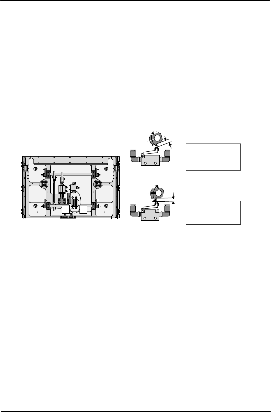
4.5 Main Table Pneumatic Switch Adjustment
Note: Before proceeding with these adjustments, confirm that the lifter plate flatness
check (4.1) is complete.
Fast Down Adjustment
1. With the lifter plate raised, adjust the position of the cam so that there is a gap of 1mm
between the cam and the pneumatic switch roller.
Fast Up Adjustment
2. With the lifter plate raised, adjust the position of the cam so that there is a gap of 3mm
between the cam and the pneumatic switch roller.
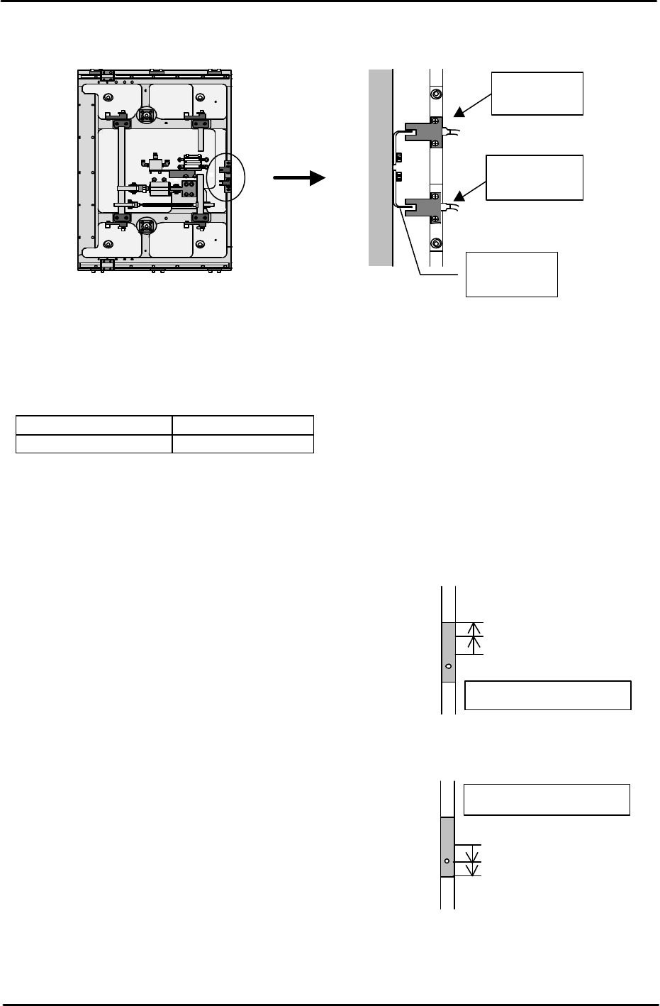
4.6 Lifter Upper/Lower Limit Sensor Adjustment
1. Raise the main lifter and adjust the flag so that the upper limit sensor turns ON when a
4mm thick board is clamped, and turns OFF when a 4.8mm thick board is clamped.
2. With the main lifter lowered, adjust the flag at the lower limit sensor side so that it is
positioned 1mm past the point where the sensor comes ON.
3. Ensure that the I/O X024 MainStLftUpChk is ON when the lifter is at its upper limit, and
X025 MainStLftDwnChk is ON when the lifter is at its lower limit.
4. Ensure that there is no vibration when the lifter is raised and lowered.
1
. Fast Down cam.
1mm gap with lifter
raised
2
. Fast UP cam.
Horizontal with lifter
raised
1
2
Machine rear under the lifter plate.
Machine front.
FK-9F98-29 XP Series Training Text for Service Engineers
Edition 5.0 XP241 – Chapter 4 Loader Adjustment Page 7 of 12
Fuji Machine Mfg. Co., Ltd. Okazaki.
SMT Equipment Quality Assurance Dept.
4 – 7 CS Section
Checking the Lifter Speed
1. Select [Manual Operation] – [Conveyor Operation] – [Main Lifter Up/Down] to raise and
lower the main lifter. The travel time should be in the following range:
Moving UP 400 – 600 ms
Moving DOWN 700 – 900 ms
Note: If the travel time is not in the range, re-adjust the main lifter speed controllers.
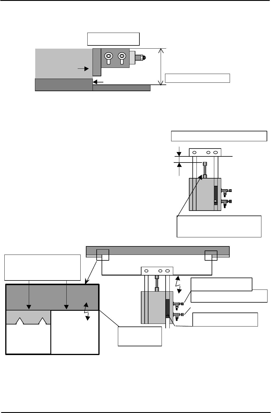
4.7 Adjusting the Main Stopper
Measuring jig: Plate jig (AJPJ-0060)
Main stopper adjustment
1. Select [Maintenance A] – [I/O Check] – and turn Y02A
MainStationStp OFF to lower the main stopper.
2. Lower the lower limit sensor (I/O X01F
MainStStpOffChk) until it turns OFF.
3. Raise the lower limit sensor, and lock the sensor 1mm
above the point it first turns ON.
4. 4.Select [Maintenance A] – [I/O Check], and turn ON
I/O Y02A MainStationStop to raise the main stopper.
5. Raise the upper limit sensor (I/O X01E
MainStStpOnChk) until it turns OFF.
6. Lower the upper limit sensor, and fasten the sensor
1mm below the point the sensor first comes ON.
7. Adjust the position of the main stopper as is shown in the following diagram:
Fix the Sensor
Sensor ON: raise 1mm
Sensor OFF
Main stopper down
Fix the sensor
Sensor ON: Lower 1mm
Sensor OFF
Main stopper up
Table
Front of the
machine
Adjust the
flag
Lower limit
sensor
Upper limit
sensor
FK-9F98-29 XP Series Training Text for Service Engineers
Edition 5.0 XP241 – Chapter 4 Loader Adjustment Page 8 of 12
Fuji Machine Mfg. Co., Ltd. Okazaki.
SMT Equipment Quality Assurance Dept.
4 – 8 CS Section
Note: Set the main stopper at a right angle to the fixed rail.
4.8 In-lifter adjustment
1. Select [Maintenance A] – [I/O Check], and turn I/O
Y02D InStLftUpChk ON to raise the in-lifter.
2. Adjust the cylinder stopper bolt so that the clearance
between the in-lifter air cylinder stopper and
underside of the lifter plate becomes 1.0mm.
3. Turn I/O Y02D InStLifterUp OFF to lower the in-lifter.
The top of the lifter plate should now be flush with the
conveyor belt top surface. If not adjust the tilt of the
lifter plate.
4. When step 3 is complete turn I/O Y02D InStLifterUp ON to raise the in-lifter.
5. Now repeat the procedure in step 2, but this time set the clearance to 1.5mm.
Plate jig
(AJPJ-0060)
Place the stopper leading edge at the
same position as the board clamper edge.
Main stopper
45 ~ 47mm
Parts No. ADEQC9201
Adjust the
clearance
to 1.0mm
To adjust the clearance, adjust
the cylinder stopper bolt
Conveyor belt
top surface
Upward limit sensor
Speed controller (DOWN)
Speed controller (UP)
Backup
Plate
Lifter Plate
Conveyor Belt
Align the height of the plate
top surface and belt top
surface.