xp141-241-341-5.0E.pdf - 第160页
FK-9F98- 29 XP Series Training Text for Service Engineers Edition 5.0 XP241 – Chapter 6 Proper Data Measurements Page 14 of 20 Fuji Machine Mfg. Co., Ltd. Okazaki. SMT Equipment Quality Assurance Dept . 6 – 14 CS Section…
FK-9F98-29 XP Series Training Text for Service Engineers
Edition 5.0 XP241 – Chapter 6 Proper Data Measurements Page 13 of 20
Fuji Machine Mfg. Co., Ltd. Okazaki.
SMT Equipment Quality Assurance Dept.
6 – 13 CS Section
12. Bring the Z-axis to the new value and select [Z_NzlPosZH] – [Direct Servo Input] to
save the maximum nozzle height in proper data.
Nozzle change station set check sensors
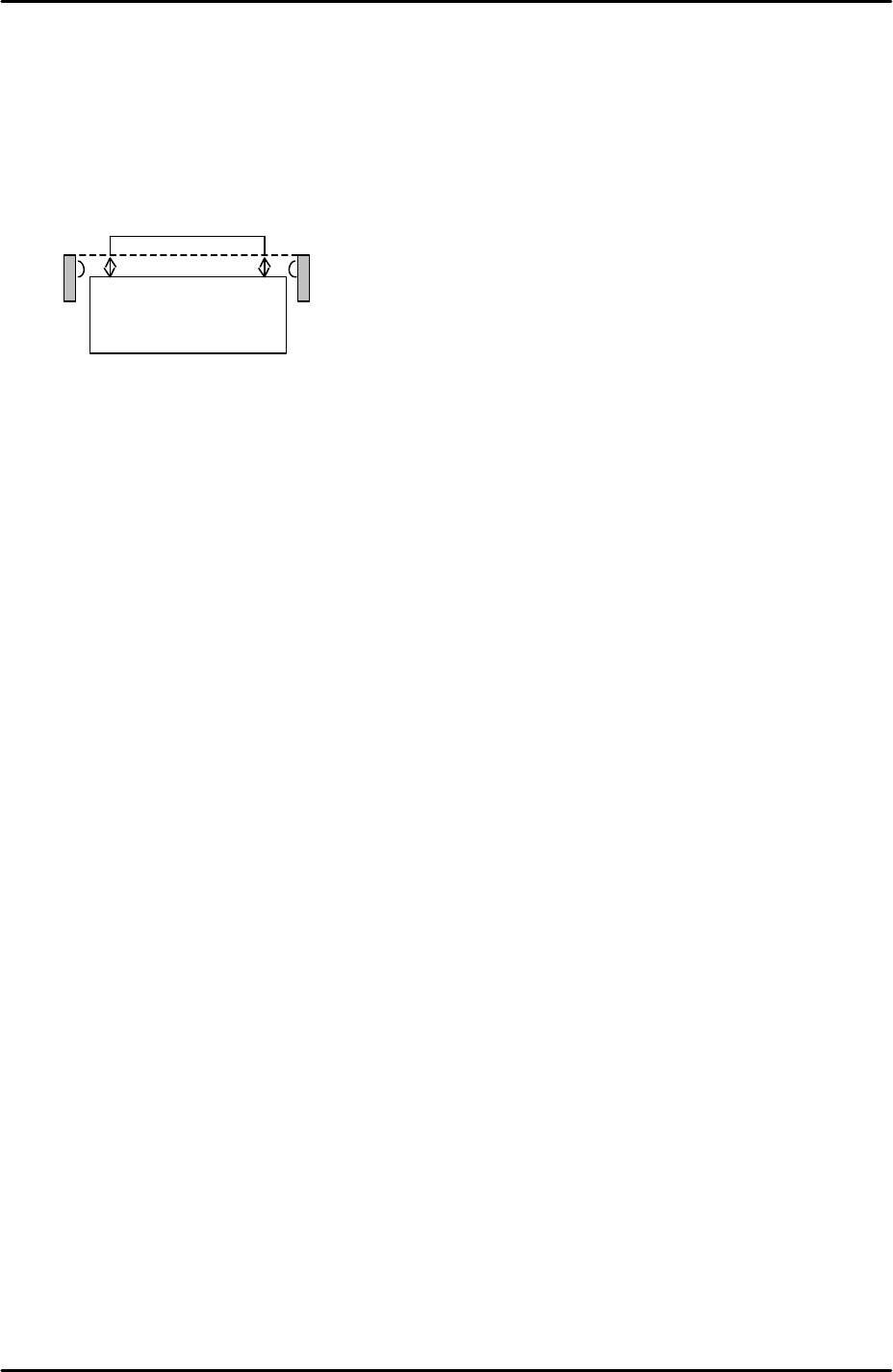
1. The position of the sensors should be adjusted so that they are between 3.5mm to
4.0mm above the nozzle change station surface:
2. To monitor the I/O signal select [Maintenance A] – [I/O Check] – [X023: NzlSetChk].
3. Adjust the position of the sensors so that the I/O is OFF when the nozzles are set
correctly in the station and ON when a 1mm feeler gage is placed on top of the
nozzles.
6.9 Nozzle place measurement
1. From the Production screen select [Nozzle Editor] and change nozzle entry 1 to
1.8mm.
2. Place a 1.8mm nozzle in the nozzle change station pocket 1.
3. Select [Maintenance C] – [Nozzle Measurement] to enter the nozzle place
measurement screen.
4. Select the [Side1_Front] camera and set the acceleration rate to 1.0.
5. Select nozzle 1 and press [Nozzle Place Measurement] – [START] to execute
nozzle place measurement. Here the placement head picks up nozzle 1 and vision
processing is carried out.
6. This measurement makes a small offset to the [X_NzlPosX1/Y_NzlPosY1] proper
data measured in 6.8. Using the vision processing system the machine can
determine the nozzle position more accurately than with the manual measurement
alone.
7. There is no need to carry out this measurement for the other nozzle positions as
they all share the same proper data [X_NzlPosX1/Y_NzlPosY1]. The distance
from nozzle position 1 to all other nozzle positions is fixed in the software.
3.5mm~ 4.0mm
Nozzle Station
FK-9F98-29 XP Series Training Text for Service Engineers
Edition 5.0 XP241 – Chapter 6 Proper Data Measurements Page 14 of 20
Fuji Machine Mfg. Co., Ltd. Okazaki.
SMT Equipment Quality Assurance Dept.
6 – 14 CS Section
6.10 Checking the operation of the nozzle station
1. From the production screen select [Nozzle Editor] and configure the nozzle entries
as described in the following table:
Nozzle Number Nozzle diameter (mm)
1 0.7
2 1.0
3 1.3
4 1.8
5 2.5
6 3.7
7 10
8 15
9 20
2. Arrange the nozzles in the nozzle station so that they match the nozzle editor
configuration.
3. Select [Manual Operation] – [Nozzle operation] – [1] – [Execute] – [START] to pick
up nozzle 1. Check that the placing head picks up the nozzle smoothly and then
select [Place] – [Execute] – [START] to return the nozzle to the nozzle station.
4. Repeat this procedure for all the remaining nozzles.
6.11 Measuring the parts reject positions
Small parts reject position
1. Select [Maintenance A] – [Jog] – [Fiducial] and display the cross hairs on the
screen.
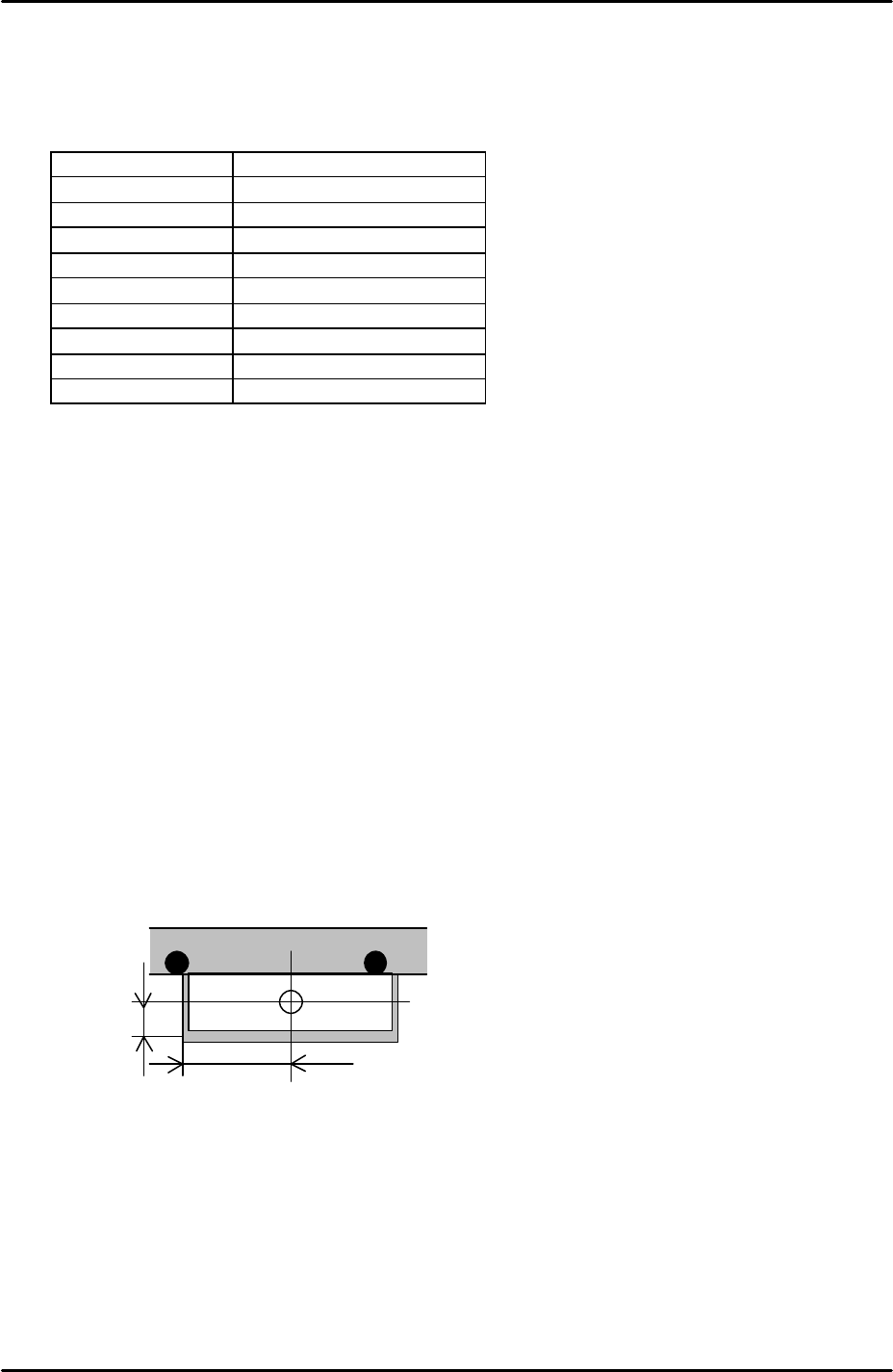
2. Jog the fiducial camera until it is in the centre of the small parts reject box on the
fixed rail. Refer to the diagram above for the dimensions of the box.
3. Select [Maintenance C] – [Proper Data Editor] – [Dispose Position] –
[X_Disposal1/Y_Disposal1] – [Direct Servo Input] to save the current X-axis and Y-
axis positions in proper data.
35mm
12.5mm
Small parts reject pos.
FK-9F98-29 XP Series Training Text for Service Engineers
Edition 5.0 XP241 – Chapter 6 Proper Data Measurements Page 15 of 20
Fuji Machine Mfg. Co., Ltd. Okazaki.
SMT Equipment Quality Assurance Dept.
6 – 15 CS Section
Large parts reject position
1. Equipment: Nozzle jig (Z95314DEPJ0070)
2. Select [Maintenance A] – [I/O check] – [Y021 NozzleUnhold] – [OFF] and attach the
nozzle jig to the placing head.
3. Select [Maintenance A] – [Jog] – and carefully inch the nozzle jig above the surface
of the reject parts tray.
4. Press the emergency stop button to cut the 200 volt power supply to the servos and
then manually descend the Z-axis until the nozzle jig contacts the surface of the
reject parts tray.
5. Select [Maintenance C] – [Proper data editor] – [Dispose position] – [Z_Disposal 2]
– [Direct servo input] to save the current Z-axis position in proper data.
6. In the case of the reject parts tray the machine software determines the position of
X and Y disposal, so the “X_Disposal 2” and “Y_Disposal 2” entries should be set to
0 by default.
6.12 Measuring the tray parts pick up position
1. Equipment: Nozzle jig (Z95361DEPJ0070). Tray pick up measurement jig
(Z9531DEPJ0040).
2. Select [Manual Operation] – [Tray Operation] – [01, 02] – [Move Elevator] –
[START] – [Advance Shuttle] – [START] to bring tray 1 to the end of the U axis.
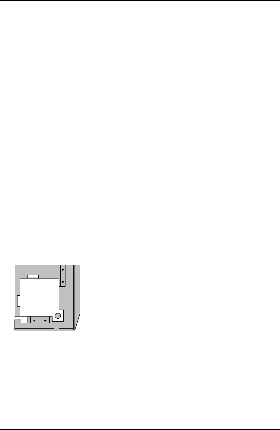
3. Set the tray pick up position jig in the front right corner of the tray as illustrated in
the following diagram:
4. Use magnets to secure the tray pick up jig in the corner of the tray.
5. Select [Maintenance A] – [I/O Check] – [Y021 NozzleUnhold] – [OFF] and attach
the nozzle jig to the placing head.
6. Bring the placing head over the tray pick up measurement jig and then press the
emergency stop button to cut the 200V power supply to the servos.
7. Manually move the X, Y and Z axes until the nozzle jig can slide smoothly into the
tray pick up position jig hole.