xp141-241-341-5.0E.pdf - 第188页
FK-9F98- 29 XP Series Training Text for Service Engineers Edition 5.0 XP241 – Chapter 9 New MTU Adjustment Page 5 of 21 Fuji Machine Mfg. Co., Ltd. Okazaki SMT Equipment Quality Assurance Dept. 9 – 5 CS Section [SERVO_LI…

FK-9F98-29 XP Series Training Text for Service Engineers
Edition 5.0 XP241 – Chapter 9 New MTU Adjustment Page 4 of 21
Fuji Machine Mfg. Co., Ltd. Okazaki
SMT Equipment Quality Assurance Dept.
9 – 4 CS Section
5. Connect the digital operator to the target servo amp (“bb” is displayed on the screen).
6. Press [DSPL/SET] to select the channel mode (Fn000).
7. Select channel (Fn008) by pressing the [UP] arrow key.
8. Press [DATA/ENTER] to display “PGCL1”.
9. Press [UP] to set it to “PGCL5”.
10. Press [DSPL/SET] and “done” displays on the screen.
11. Press [DATA/ENTER] to return to the support mode (Fn008).
12. Press [DOWN] to return to the channel mode (Fn000).
13. Press [DSPL/SET] to return to the initial screen (“bb” displays).
14. When the settings are complete select [Maintenance C] – [Proper Data Editor] –
[SERVO_OFST] – and set [_targetOfst_T] and [_targetOfst_U] to 0.
15. Shut down and then restart the machine.
9.7 Setting the origin and minus limit
1. Select [Maintenance C] – [Proper Data Editor] – [SERVO_OFST] – and confirm that
[_targetOfst_T] and [_targetOfst_U] are set to 0.
2. Turn the servo power ON and then select [Maintenance A] – [Jog] – [T,U] to display the T
and U axis counter values.
3. Press the [Emergency Stop] button, and confirm that the T and U axes are against their
minus mechanical stoppers.
4. Record the counter value of both axes. The counter value is in (mm) but this must be
converted into (1/10um) before inputting in proper data. For example counter value
18.252100 (mm) Ü input value 182521.
5. Select [Maintenance C] – [Proper Data Editor] – [SERVO_OFST] – [_targetOfst_T] and
[_targetOfst_U] and input the counter value recorded in step 4.
6. Check that the target offset is within the tolerance specified in the following table:
Target Offset Target Offset Tolerance
_targetOfst_T 0 +/- 100000
_targetOfst_U 0 +/- 200000
7. Select [Jog] to return to the jog screen and turn the servo power ON. The counter values
for the T and U axes should be close to “0”. A counter value that is not close to “0”
indicates that an inaccurate target offset has been input. In this case input the target
offset again.
8. When the origin setting is complete select [Maintenance C] – [Proper Data Editor] –
FK-9F98-29 XP Series Training Text for Service Engineers
Edition 5.0 XP241 – Chapter 9 New MTU Adjustment Page 5 of 21
Fuji Machine Mfg. Co., Ltd. Okazaki
SMT Equipment Quality Assurance Dept.
9 – 5 CS Section
[SERVO_LIMIT] and set [T_MinusLimit] and [U_MinusLimit] to “0”.
9. Finally shutdown and then restart the machine.
9.8 Setting the plus limit
1. Remove the tray catch stopper from the U axis plus limit side.
2. Move the T and the U axes to their plus mechanical stoppers and select [Maintenance C]
– [Proper Data Editor] – [SERVO_LIMIT] – [T_PlusLimit] and [U_PlusLimit] – [Direct
Servo Input] to save the current counter value to proper data.
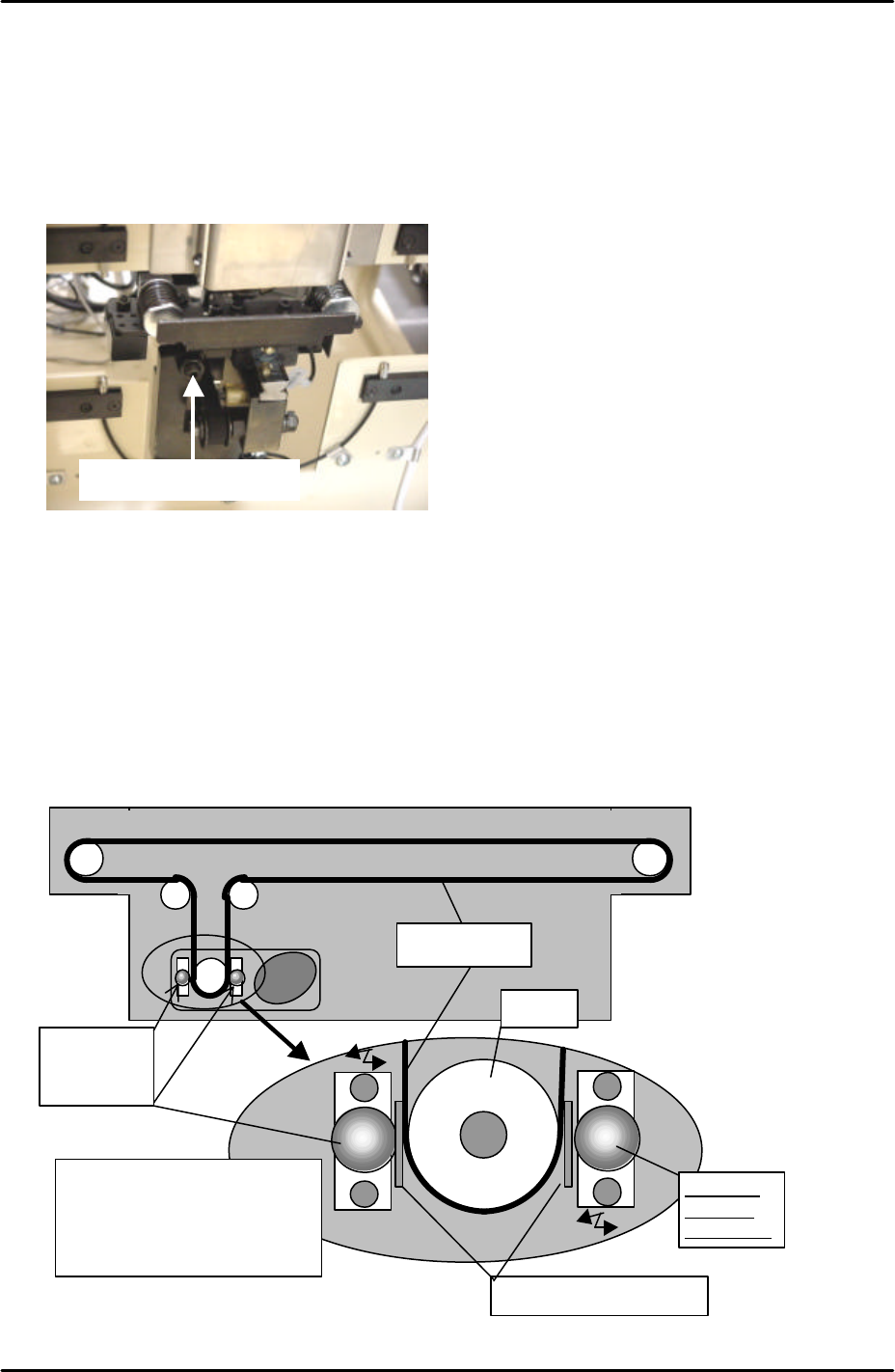
9.9 U-Axis belt slippage adjustment
1. Use a feeler gage and adjust the roller guide so that the distance between the roller and
the belt becomes 0.1mm.
Tray Catch Stopper
Roller for
slippage
prevention
Pulley
0.1mm feeler gauge
Roller for
slippage
prevention
Insert the feeler gauge
between the pulley and roller.
Push the roller against the
pulley and tighten the bolt.
Timing belt
FK-9F98-29 XP Series Training Text for Service Engineers
Edition 5.0 XP241 – Chapter 9 New MTU Adjustment Page 6 of 21
Fuji Machine Mfg. Co., Ltd. Okazaki
SMT Equipment Quality Assurance Dept.
9 – 6 CS Section
2. Verify that the roller rotates with the belt when the belt is pulled manually.
3. Remove the jumper and replace the “35BKT1-CN2” cable in the side 1 electric box and
confirm the brake is on even when the servo power is OFF.
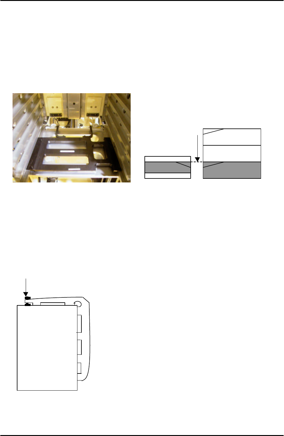
9.10 T-Tray origin (magazine adjustment and measurement)
1. Jog the T-axis until the right hand side of slot [41,42] is level with the U axis conveyor rail.
Use the dial gages and jig (Z9731ADEPJ8131):
2. With the T-axis in the same position measure the height difference between the left side
of slot [41, 42] and the U axis conveyor rail. The height of the magazine slot should be
0.03mm higher than that of the U axis conveyor rail. The reason for this is that the MTU
magazine is fixed at the right hand side (when viewed from the machine rear) but not at
the left-hand side. When trays and tray parts are loaded on the left-hand side it is
weighed down and lowers slightly in relation to the right hand side.
3. If necessary adjust the height of the left hand side of slot [41,42] using the bolt on top of
the magazine, see diagram below:
4. Jog the T axis so that slot [01,02] is roughly level with the U axis conveyor rail.
5. Use the dial gage and jig to find the position where the right hand side of slot [01,02] is
0.04mm above the U axis conveyor rail.
Adjust here
Magazine [41,42]
U axis
The U axis conveyor
and slot [41,42] of the
magazine are level