xp141-241-341-5.0E.pdf - 第78页
FK-9F98- 29 XP Series Training Text for Service Engineers Edition 5.0 XP141 – Chapter 6 Proper Data Measurements Page 23 of 26 Fuji Machine Mfg. Co., Ltd. Okazaki SMT Equipment Quality Assurance Dept. 6 – 23 CS Section 5…
FK-9F98-29 XP Series Training Text for Service Engineers
Edition 5.0 XP141 – Chapter 6 Proper Data Measurements Page 22 of 26
Fuji Machine Mfg. Co., Ltd. Okazaki
SMT Equipment Quality Assurance Dept.
6 – 22 CS Section
6.18 X and Y axis retract position
1. The retract position ensures the placing head is not in a position that would cause
interference when clamping or unclamping an MFU from the machine.
2. Select [Maintenance C] – [Proper Data Editor] – [Machine Origin] – and check that the
following proper data is input:
X_Table Org 5mm
Y_Table Org 400mm
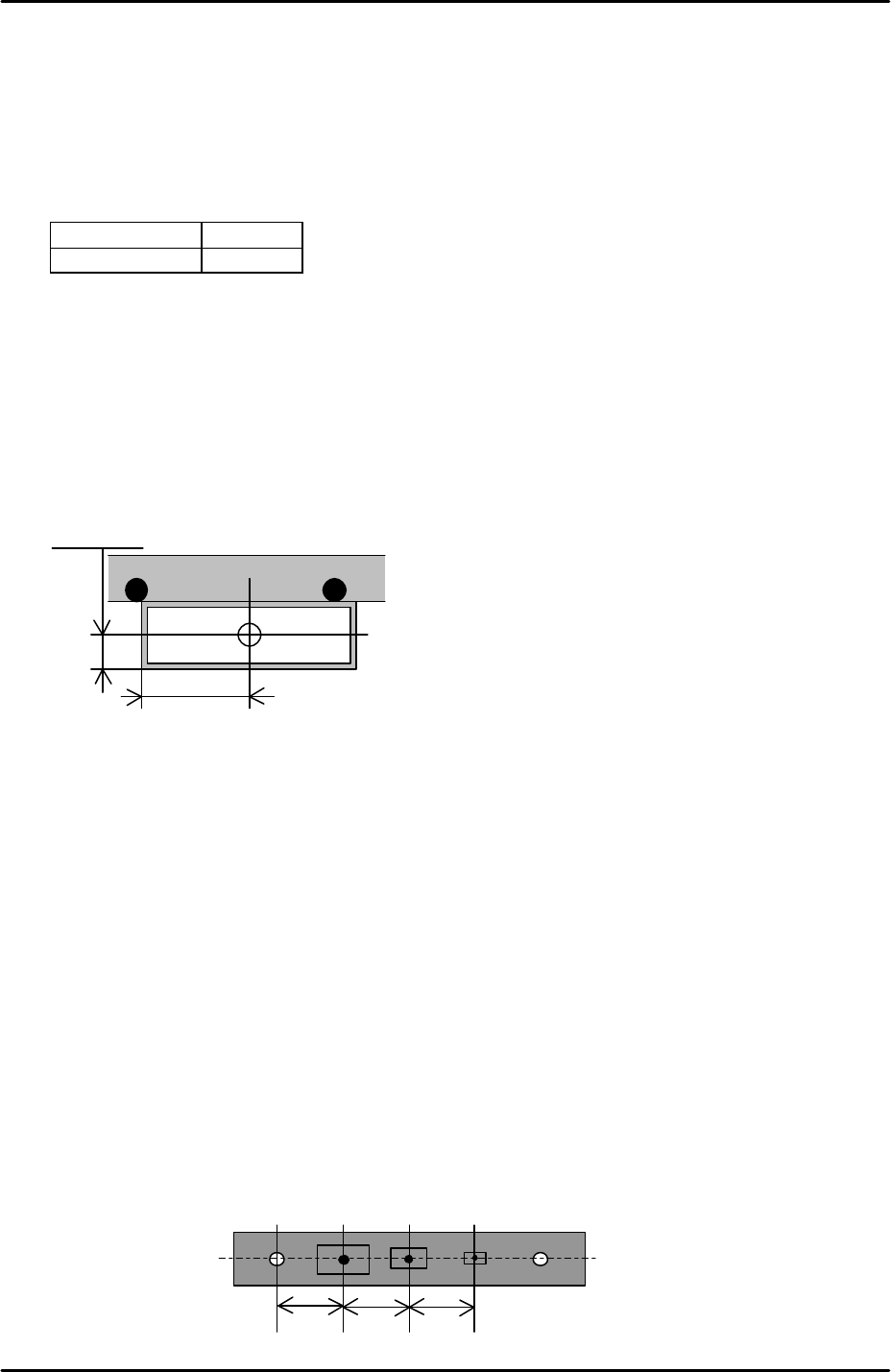
6.19 Measuring the parts reject position
1. Select [Maintenance A] – [Jog] – [Fiducial Camera] and display the cross hairs on the
screen.
2. Jog the fiducial camera until it is in the center of the parts reject box. Refer to the
diagram below for the dimensions of the box:
3. Select [Maintenance C] – [Proper Data Editor] – [Dispose Position] –
[X_Disposal1/Y_Disposal1] – [Direct Servo Input] to save the current X-axis and Y-axis
positions in proper data.
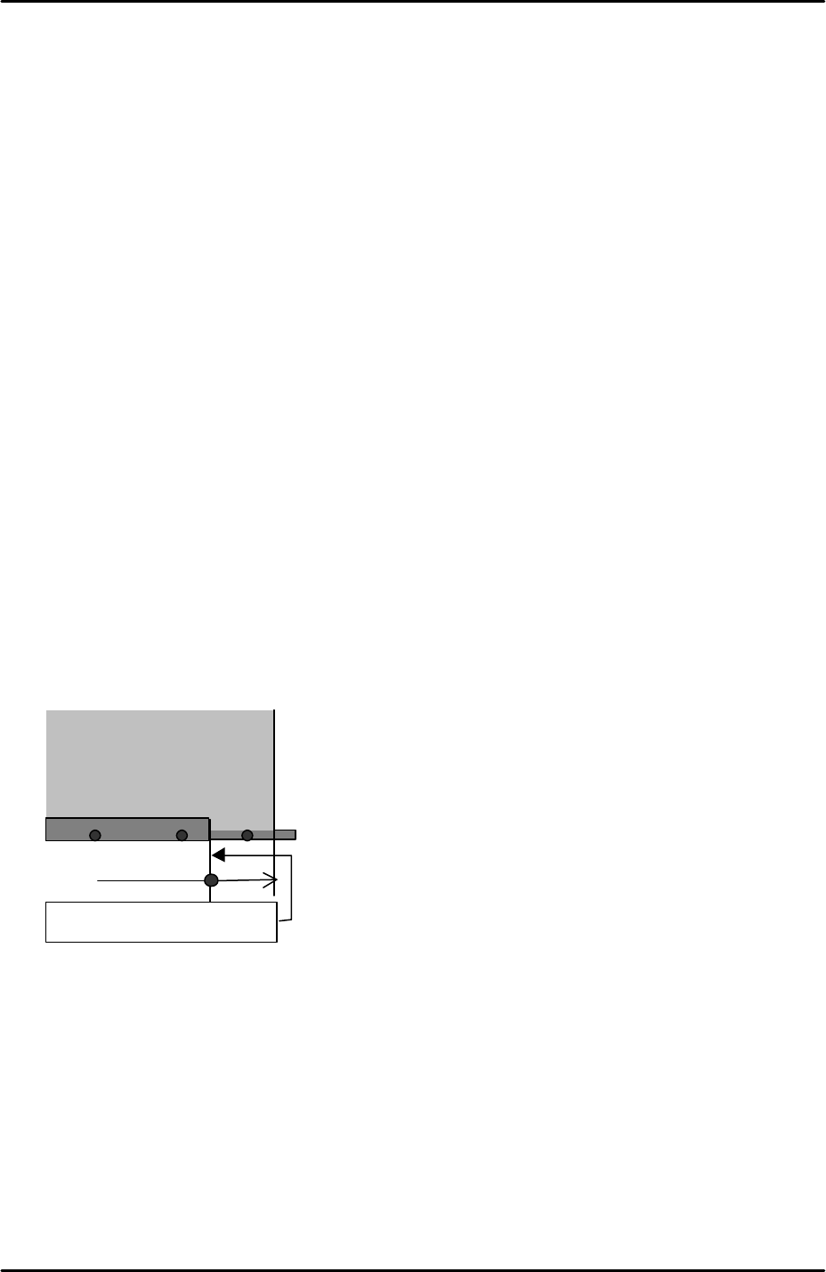
6.20 Measuring the parts gage pickup positions
1. Equipment: nozzle jig (A5706ASEAJ8100). Lever type dial gage (0.01mm).
2. Select [Maintenance A] – [Jog] – [Fiducial Camera] and display the cross hairs.
3. Carefully remove the three ceramic parts gages from the parts gage station so that the
parts gage indents and vacuum holes are visible.
4. Center the cross hairs on the parts gage 1 vacuum hole and select [Maintenance C] –
[Proper Data Editor] – [Jig Position] – [Y_JigPickPos] – [Direct Servo Input] and
[X_JigPickPos1] – [Direct Servo Input] to save the current X and Y axis counter values to
proper data.
12.5mm
35mm
10 1010
1 2 3A
FK-9F98-29 XP Series Training Text for Service Engineers
Edition 5.0 XP141 – Chapter 6 Proper Data Measurements Page 23 of 26
Fuji Machine Mfg. Co., Ltd. Okazaki
SMT Equipment Quality Assurance Dept.
6 – 23 CS Section
5. Return to the jog screen and center the cross hairs on the parts gage 2 vacuum hole and
select [X_JigPickPos2] – [Direct Servo Input] to save the current X axis counter value to
proper data.
6. Return to the jog screen and center the cross hairs on the parts gage 3 vacuum hole and
select [X_JigPickPos3] – [Direct Servo Input] to save the current X-axis counter value to
proper data.
7. Insert the nozzle jig in nozzle piston no.1 and replace the no.1 parts gage in the parts
gage station.
8. Bring the nozzle jig above the parts gage and descend the Z-axis until the nozzle jig
almost contacts the parts gage.
9. Place a dial gage on the nozzle jig and use this to determine the point where the nozzle
jig first contacts the parts gage.
10. Select [Z_JigPickPos] – [Direct Servo Input] to save the current Z-axis counter value to
proper data.
6.21 Measuring the matrix data
1. Equipment: glass gage for matrix measurement (A5704DEAJ14013).
2. Note that the matrix data measurement should be carried out when the machine is cold,
otherwise the results will not be reliable. Fuji recommends that the machine is not used
for at least two hours prior to the measurement.
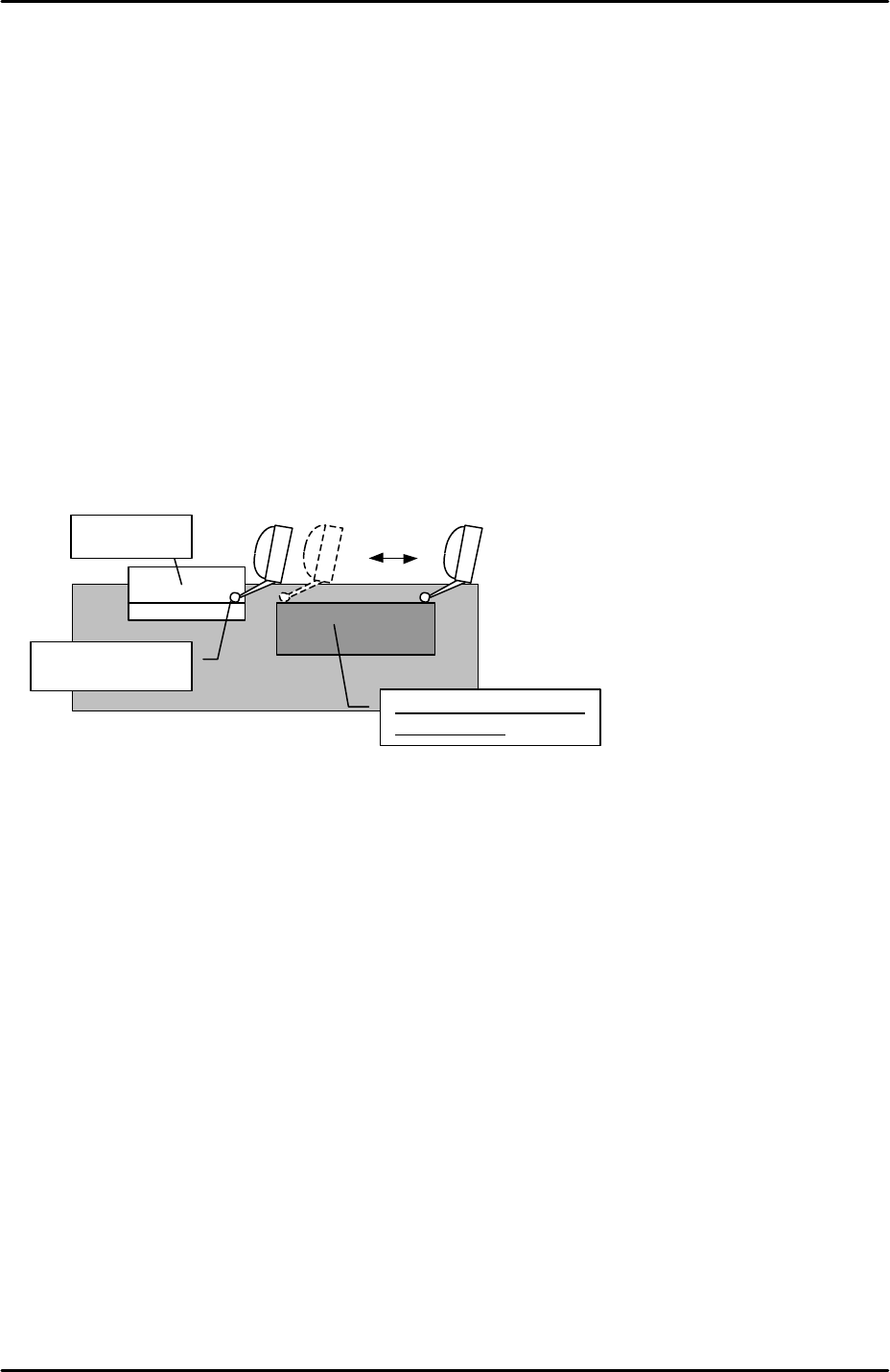
3. Clamp the matrix measurement glass gage approximately 70mm from the main conveyor
right end.
4. Because the glass gage is 5mm thick the main lifter upper limit sensor will not come ON
when the gage is clamped. As a result it is necessary to interrupt the upper limit sensor
with a piece of paper tape.
5. Select [Maintenance A] – [Jog] – [Fiducial camera] – and display the cross hairs on the
screen.
6. Center the fiducial camera on the last dot in the bottom left hand corner of the glass gage
and record the Y-axis counter value.
7. Move the fiducial camera until it is centered on the last dot in the bottom right hand
corner of the glass gage. Compare the current Y-axis counter value with that recorded in
step 6. The difference in value should be within 0.5mm. This ensures that the X-axis
Glass gauge for matrix data
( A5704DEAJ1013)
Approx. 70mm
Main conveyor right end
FK-9F98-29 XP Series Training Text for Service Engineers
Edition 5.0 XP141 – Chapter 6 Proper Data Measurements Page 24 of 26
Fuji Machine Mfg. Co., Ltd. Okazaki
SMT Equipment Quality Assurance Dept.
6 – 24 CS Section
and the glass gage are parallel.
8. With the fiducial camera still centered on the last dot in the bottom right hand corner of
the glass gage select [Maintenance C] – [Matrix data measurement] – and set the
acceleration rate to 1.0 before selecting [Start].
9. The measurement will take approximately 1 hour to complete. Matrix data measurement
is designed to compensate for minute discrepancies in the straightness of the X and Y-
axis ball screws. The measurement is performed in the factory prior to machine shipment
and is not normally performed again.
6.22 Adjusting the conveyor automatic width changer
1. Equipment: lever type dial gage (0.01mm). Width defining mark bracket height
adjustment jig (A9531DEPJ1250).
2. Set the jig adjacent to the width defining mark bracket on the adjustable rail.
3. Set the dial gage to 0 on the reference side of the jig and slide it across the width defining
mark bracket.
4. Adjust the height of the bracket so that it is the same height as the jig (tolerance +/-
0.05mm). The flatness of the bracket should be within 0.05mm.
5. Set the conveyor width to approximately 100mm.
6. Select [Maintenance A] – [Jog] – [Fiducial] – and display the cross hairs on the screen.
7. Center the fiducial camera on the glass gage station fiducial mark and record the X-axis
counter value at this position.
8. Inch the fiducial camera in the Y direction until the width defining bracket comes into
view, then center the camera on the width defining mark.
9. Record the X-axis counter value at this position and subtract this figure from the X axis
counter value recorded in step 7. This value is the “ConvWidthMarkDiffX” proper data.
10. Select [Maintenance C] – [Proper data editor] – [Others] – [ConvWidthMarkDiffX] – and
manually input the figure calculated at step 9.
Height jig
Set the dial to “0”
Flatness
s
ho
u
ld be
within 0.05mm