xp141-241-341-5.0E.pdf - 第192页
FK-9F98- 29 XP Series Training Text for Service Engineers Edition 5.0 XP241 – Chapter 9 New MTU Adjustment Page 9 of 21 Fuji Machine Mfg. Co., Ltd. Okazaki SMT Equipment Quality Assurance Dept. 9 – 9 CS Section eccentric…
FK-9F98-29 XP Series Training Text for Service Engineers
Edition 5.0 XP241 – Chapter 9 New MTU Adjustment Page 8 of 21
Fuji Machine Mfg. Co., Ltd. Okazaki
SMT Equipment Quality Assurance Dept.
9 – 8 CS Section
2. Adjust the position of the shuttle rails so that they are aligned with the reference slot,
tolerance is 0.05mm.
3. Be careful when measuring the alignment as the first few centimeters of the shuttle rails
are tapered. Measure at the point where the shuttle rail is straight.
9.14 Tray pusher adjustment 1
1. Set the speed controllers for the tray pusher as follows:
2. Turn I/O Y033: TrayPusherBwd OFF, and I/O Y032 TrayPusherFwd ON to bring the
pusher to its forward position.
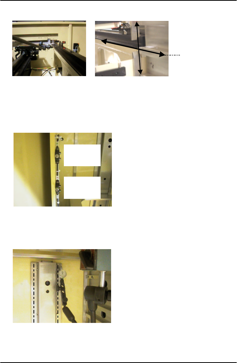
3. Attach a dial gage stand to the magazine and set the dial gage tip on the pusher as
shown below:
4. Measure the flatness of the left and right hand pusher panels. Measure from top to
bottom as illustrated by the dotted lines in the photo above.
5. If necessary loosen the installation bolts on the panels, and adjust the flatness with the
Measure along this line
Fwd: ¾ turn
from fully
closed
Bwd: 5 turns
from fully
closed
FK-9F98-29 XP Series Training Text for Service Engineers
Edition 5.0 XP241 – Chapter 9 New MTU Adjustment Page 9 of 21
Fuji Machine Mfg. Co., Ltd. Okazaki
SMT Equipment Quality Assurance Dept.
9 – 9 CS Section
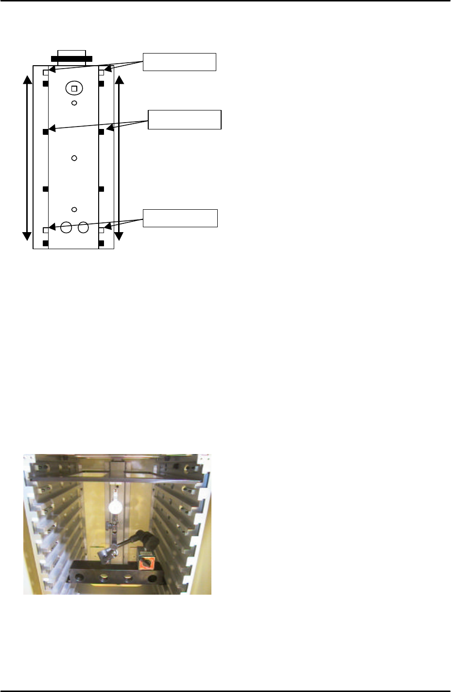
eccentric pin. Adjust so that the dial gage reads 0 at the top of the pusher and 0 at the
bottom. Also measure the points in between, tolerance is +/-0.15mm
9.15 Tray Pusher Adjustment 2
1. Reverse the I/Os set in the previous adjustment. Turn Y032 TrayPusherFwd OFF, and
Y033: TrayPusherBwd ON.
2. Set the T axis 3mm below the + limit.
3. Set the tray pallet jig (Z9631DEPJ3740) in the magazine top slot, and set a magnet on
the underside. Confirm that the tray pallet jig is in contact with the guide bar.
4. Set the large block jig (Z9631ADEPJ8172) in slot [41,42].
5. Set the dial stand on the block jig and the dial gage to 0 on the magnet as shown below:
6. Descend the T-axis and watch the dial gage to find the position where the guide bar is
most forward.
7. Bring the T-axis back to 3mm below the + limit and set the tray pallet jig in the slot that is
in the position where the guide bar is most forward.
Fulcrum Pin
Eccentric Pin
Fixing Bolts
FK-9F98-29 XP Series Training Text for Service Engineers
Edition 5.0 XP241 – Chapter 9 New MTU Adjustment Page 10 of 21
Fuji Machine Mfg. Co., Ltd. Okazaki
SMT Equipment Quality Assurance Dept.
9 – 10 CS Section
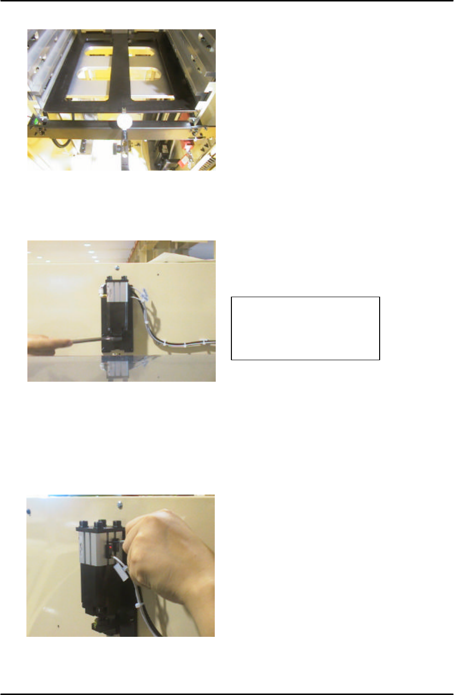
8. Set the dial gage to 0 on the tray pallet jig as shown below:
9. Turn I/O TrayPusherBwd OFF, and I/O Y032 TrayPusherFwd ON to bring the pusher to
its forward position. The dial gage should indicate that the tray pallet jig has moved
0.5mm forward. If not it is necessary to adjust the cylinder stroke at the back of the MTU:
10. Move the tray pusher forward and find the position where the forward end sensor (X03E:
TrayPusherFwChk) first comes ON. From this position set the sensor a further 0.5mm in
the ON direction.
11. Move the tray pusher backward and find the position where the backward end sensor
(X03F TrayPusherBwChk) first comes ON. From this position set the sensor a further
0.5mm in the ON direction.
Adjust the cylinder stroke
so that when the pusher is
activated the tray pallet is
pushed 0.5mm.