xp141-241-341-5.0E.pdf - 第133页
FK-9F98- 29 XP Series training Text for Service Engineers Edition 5.0 XP241 – Chapter 5 Peripheral Adjustments Page 8 of 19 Fuji Machine Mfg. Co., Ltd. Okazaki. SMT Equipment Quality Assurance Dept . 5 – 8 CS Section 4. …
FK-9F98-29 XP Series training Text for Service Engineers
Edition 5.0 XP241 – Chapter 5 Peripheral Adjustments Page 7 of 19
Fuji Machine Mfg. Co., Ltd. Okazaki.
SMT Equipment Quality Assurance Dept.
5 – 7 CS Section
Note: the following proper data settings refer to software version 1.12e and later. The proper
data item referred to is “Tray Eject Check” in machine operation. The default setting for new
machines is 2.
Proper data setting Status Sensor Location
0 Tray eject check is inactive. Either location.
1 Tray eject check is active. At the rear of the nozzle change station.
2 Tray eject check is active. At the tray eject area.
5.2 Adjusting the MFU
Measuring equipment: Lever type dial gauge (0.01mm).
Feeder flatness and parallelism measurements
1. Adjust the MFU air valve speed controllers as follows:
Speed controller location Number of turns from fully closed Function
Upper speed controllers 2 turns from fully closed Unclamp
Lower speed controllers 1.5 turns from fully closed Clamp
Note: ensure that there is no jolting when clamping and unclamping the MFU.
2. Clamp the MFU to the machine.
Warning: the MFU device table is very heavy. Please take extreme care to prevent your
finger/hand getting caught when carrying out height or other adjustments on the MFU.
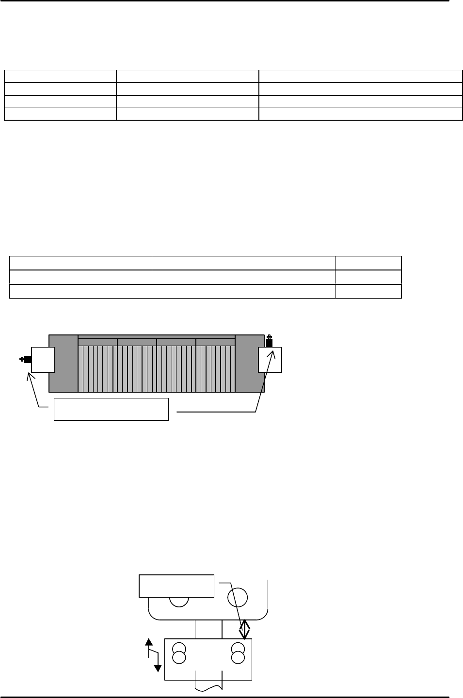
3. Adjust the MFU adjustment stopper, so that when the MFU is clamped, the gap between
the stopper and the MFU device table underside is approximately 20mm. Please see the
diagram below:
Approx. 20mm
D0 D40MFU
MFU Air valves
FK-9F98-29 XP Series training Text for Service Engineers
Edition 5.0 XP241 – Chapter 5 Peripheral Adjustments Page 8 of 19
Fuji Machine Mfg. Co., Ltd. Okazaki.
SMT Equipment Quality Assurance Dept.
5 – 8 CS Section
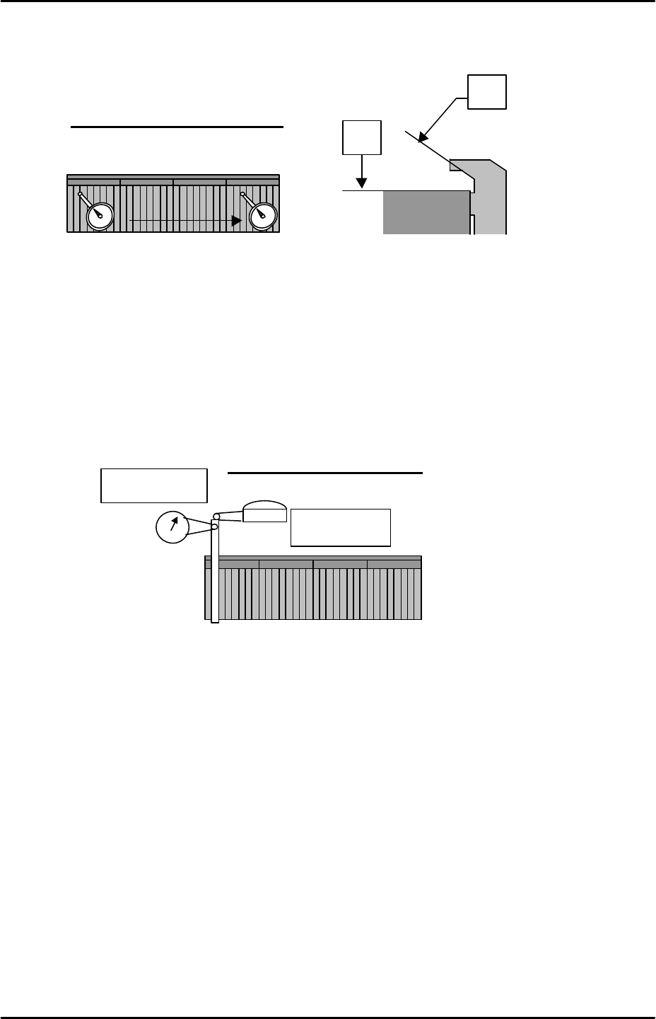
4. Use a dial gage to measure the device surface A and B. Please refer to the diagram
below:
5. Measure any additional MFUs in the same manner.
6. After measuring all of the MFUs, check the static accuracy of the MFUs at the clamping
position.
7. Choose one device as the reference MFU, and clamp the MFU to side 1.
8. Mount the device jig in slot No.2. Use an extension bar to attach the dial gage to the
placement head. Put the tip of the dial gage to the device jig in the Z and Y directions.
Please refer to the illustration:
9. Set the dial to 0. Jog the head in the X-direction so that the dial gage tip leaves the jig.
Record the present Y-axis servo count, and then unclamp the MFU.
10. Clamp the other MFU.
11. After clamping the MFU, mount the device jig in slot No.2 and turn the servo ON. Jog the
X-axis and check the difference between the position of the two MFUs in the Y and Z
directions.
12. Repeat the procedure for any other MFUs.
X direction static accuracy check
1. Clamp the reference MFU used in previous steps to side 1.
2. Mount the device jig to device No.2 and set the dial gauge tip to the X-direction.
A
B
0
D1
D40
Tolerance: 0.05 mm / 800mm
Z-direction
Y-direction
Tolerance: within 0.050mm

FK-9F98-29 XP Series training Text for Service Engineers
Edition 5.0 XP241 – Chapter 5 Peripheral Adjustments Page 9 of 19
Fuji Machine Mfg. Co., Ltd. Okazaki.
SMT Equipment Quality Assurance Dept.
5 – 9 CS Section
3. Set the dial to 0. Jog in the Y-direction to detach the dial gage tip from the jig. Record the
present X-axis servo counter. Unclamp the MFU.
4. Clamp another MFU, then mount the device jig to device No.2 and turn the servo ON. Jog
the X axis and check the difference in the X-direction.
5. Repeat the procedure for any other MFUs
Device I/O port check
1. Load the device I/O check feeder on the device table, and use direct I/O (Y040
PartsSendD1) and (Y07F PartsSendD40) to check that all the device position I/0s are
operational.
Note: Use some cloth to wipe any dirt from the MFU connectors.
5.3 MFU sensor adjustments
MFU tape leaf check sensors
Currently there are two different types of MFU tape leaf check sensors, both types are
manufactured by Yamatake. The serial number for the old LED type is: HPJ-T23. The
serial number for the newer double detection fiber type sensor is: HPF-T003 (Fiber) and
FE-PA-S1 (Attachment). The double detection fiber type sensors are supported from
machine software version V1.40 for XP241E.
Yamatake LED type (HPJ-T23)
1. Attach the MFU to the machine. Check that I/O X02D Side 1 MfuConChek turns ON.
2. Mount the feeder leaf check sensor adjustment jig (Z9631ADEPJ980) at device positions
D38 & 40 on Side 1.
3. Insert the 1.8 mm diameter rod jig in both slits, and and temporarily adjust the sensor so
that the beam beam passes through the center of the jig. Also check that the sensor is not
tilted.
4. Move the jig to D1 & D3, temporarily adjust the sensor receiver side.
X-direction
Tolerance: within 0.050mm