'操作说明 Hotflow THREE_26_zh.pdf - 第474页
T ranslation of the original ENGLISH 2. DESCRIPTION OF THE COOLING UNIT 451820.66.03_EN 2020-05-05 17 2. DESCRIPTION OF THE COOLING UNIT The cooling unit is a ready-to-use system with refrigerant circuit and water circui…

1. FOR YOUR SAFETY ENGLISH Translation of the original
16
451820.66.03_EN
2020-05-05
Translation of the original ENGLISH 2. DESCRIPTION OF THE COOLING UNIT
451820.66.03_EN
2020-05-05
17
2. DESCRIPTION OF THE COOLING UNIT
The cooling unit is a ready-to-use system with refrigerant circuit and water circuit complete with all
fittings and control devices required for automatic operation.
The heat extracted from the water is released into the surrounding air via the refrigerant circuit using
the fans.
2.1 Refrigerant circuit
The refrigerant circuit is a closed system in which the refrigerant is circulated as the working
medium.
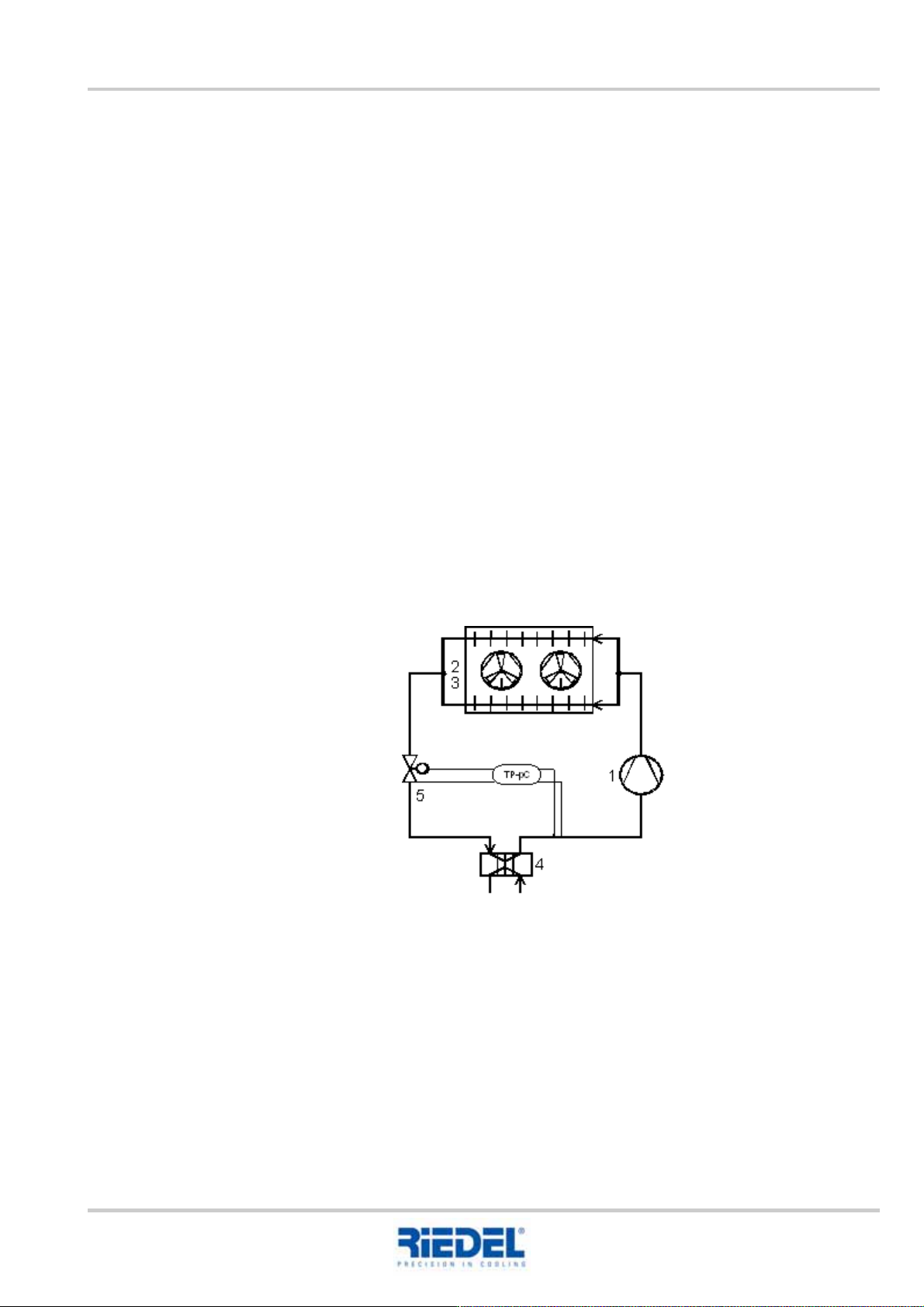
The water heated by the consumer is re-cooled in the evaporator (4). During this process, the liquid
refrigerant is routed in the opposite direction to the water flow. As a result of absorbing the waste
heat from the consumer’s cooling water, the refrigerant evaporates.
The refrigerant, now in gaseous form, is drawn in and compressed by the compressor (1) (pressure
and temperature increase). The energy from the compressor is also taken up by the refrigerant and
released into the surrounding air as waste heat by the liquefiers (2) with the help of the fan (3).
As a result, the refrigerant is liquefied and passes via the liquid receiver, isolating valve, filter dryer
and sight glass in front of the expansion valve (5). This allows liquid refrigerant into the evaporator
depending on the temperature.
The circuit is now closed.
The refrigeration capacity is regulated by switching the compressors on and off.
Block flow diagram, refrigerant circuit
2. DESCRIPTION OF THE COOLING UNIT ENGLISH Translation of the original
18
451820.66.03_EN
2020-05-05
2.2 Water circuit
Depending on requirements, the cooling unit is equipped with one of the three water circuits
described below.
(See RI flow diagram)
2.2.1 Single-circuit system with tank
With its integrated tank, the water circuit is designed as an atmospherically open system. The water
volume in the tank determines the temperature stability of the water outlet temperature. The pump
supplies the water from the tank to the consumer and via the evaporator to the tank.
2.2.2 Dual-circuit system with tank
With its integrated tank, the water circuit is designed as an atmospherically open system. The water
volume in the tank determines the temperature stability of the water outlet temperature.
The primary pump feeds water from the tank/secondary circuit back into the tank via the evaporator.
The secondary pump feeds the water from the tank back into the primary circuit via the consumer.
2.2.3 Pass-through system
The water circuit of the cooling unit is designed as an atmospherically closed system without
purging facilities. The pump feeds the water through the circuit via the evaporator and consumer.
Purging facilities must be implemented in the external water circuit.
2.3 Cooling air supply
The heat output to be extracted while cooling the water in the evaporator, as well as the electrical
drive output of the compressor, is taken up by the refrigerant and released into the cooling air in the
liquefier.
The cooling air is the surrounding air, which is sucked up by the fan(s) via the liquefier, heated up
and blown out at the top.
Unobstructed intake and outlet of cooling air in the specified temperature range must be
ensured, as must an adequate air exchange for extracting heat from the installation location
of the cooling unit.
(See chapter 5 "Installation")