'操作说明 Hotflow THREE_26_zh.pdf - 第502页
T ranslation of the original ENGLISH 1 1. OPERA TION 451820.66.03_EN 2020-05-05 45 1 1. OPERA TION The cooling unit is switched on with the mains disconnecting device (main switch). This switch also acts as the EMERGENCY…

10. ENVIRONMENTAL REQUIREMENTS ENGLISH Translation of the original
44
451820.66.03_EN
2020-05-05
Translation of the original ENGLISH 11. OPERATION
451820.66.03_EN
2020-05-05
45
11. OPERATION
The cooling unit is switched on with the mains disconnecting device (main switch). This switch also
acts as the EMERGENCY STOP switch.
The cooling unit is ready for operation and the control and operating unit is now regulating the water
outlet temperature.
It is not possible to carry out commissioning when there is a signal pending denoting a water
shortage or dry run protection.
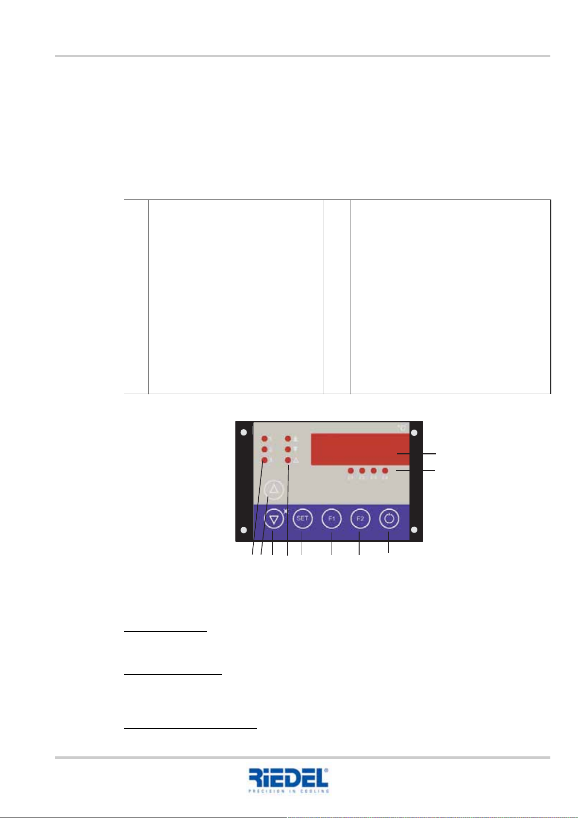
11.1 Control and operating unit ST 501
Control and operating unit ST 501
Actual values
Version with tank:
In the basic state, the flow temperature of the water circuit is shown in the display.
Version without tank:
In the basic state, the return temperature of the water circuit is shown in the display.
Press key F2 to display the flow temperature.
Adjusting the setpoint value:
To configure the setpoint value, press the SET key as well as the UP or DOWN key.
1
2
3
4
5
Display
Status displays
E1 Status – pump + water level
E2 Status – high pressure
E3 Status – low pressure
E4 Status – TC fan
Control stages
1 Pump on
2 Control stage 1 on
3 Control stage 2 on
UP key
Increase setpoint value or parameter
value
DOWN key
Decrease setpoint value or parameter
value
6
7
8
9
10
Alarm displays
"Up arrow" Fixed-setpoint regulation up for
differential regulation
"Down arrow" Fixed-setpoint regulation
down for differential regulation
"Alarm" Centralised fault indication
SET Calls the setpoint value or parameter
display
F1 key -> special function following parame-
ter release
F2 key -> special function following parame-
ter release
Stand by key
Controller on/off option
1
2
3
SET
E1
E2 E3
E4
F1
F2
°C
1
2
3 4 5 6 7 8 9 10
11. OPERATION ENGLISH Translation of the original
46
451820.66.03_EN
2020-05-05
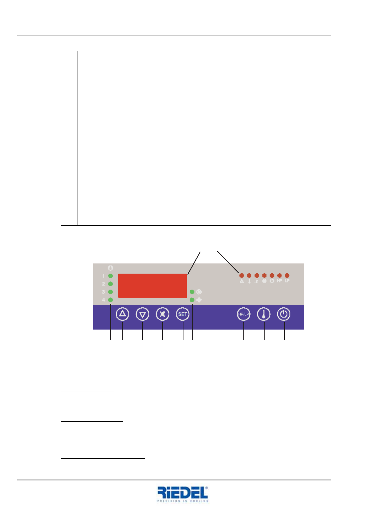
11.2 Control and operating unit ST 181
Control and operating unit ST 181
Actual values
Version with tank:
In the basic state, the flow temperature of the water circuit is shown in the display.
Version without tank:
In the basic state, the return temperature of the water circuit is shown in the display.
The "Temperature" key (item 10) can be used to display the flow temperature.
Adjusting the setpoint value:
To configure the setpoint value, press the SET key as well as the UP or DOWN key.
1
2
3
4
5
6
Display
Status displays alarm
Collective alarm
Temperature alarm
Water shortage
Pump
Cooling
High pressure HP
Low pressure LP
Control stages
1 Control stage 1 on
2 Control stage 2 on
3 Control stage 3 on
4 Control stage 4 on
UP key
Increase setpoint value or parameter
value
DOWN key
Decrease setpoint value or parameter
value
Horn key
Press once horn off
Press twice acknowledge alarm
7
8
9
10
11
SET call up the setpoint value
S1 (compressor control)
S2 (PID setpoint value)
Status displays
Pump
Fan
HP/LP key
Measured value HP sensor -> hold down
HP/LP key
Measured value LP sensor -> hold down
HP/LP + DOWN key
Temperature key
Measured value sensor F5 -> hold down
"Temperature" key
Measured value guide value sensor -> hold
down "Temperature" key + DOWN key
Measured value flow sensor -> hold down
"Temperature" key + UP key
Stand by key
Controller on/off
12
345678 91011