'操作说明 Hotflow THREE_26_zh.pdf - 第540页
T ranslation of the original ENGLISH 15. OPTIONS AND ACCESSORIES 451820.66.03_EN 2020-05-05 83 15. OPTIONS AND ACCESSORIES 15.1 Refrigerant circuit 15.1.1 Pressure gauge The pressure gauge indicates the refrigerant press…
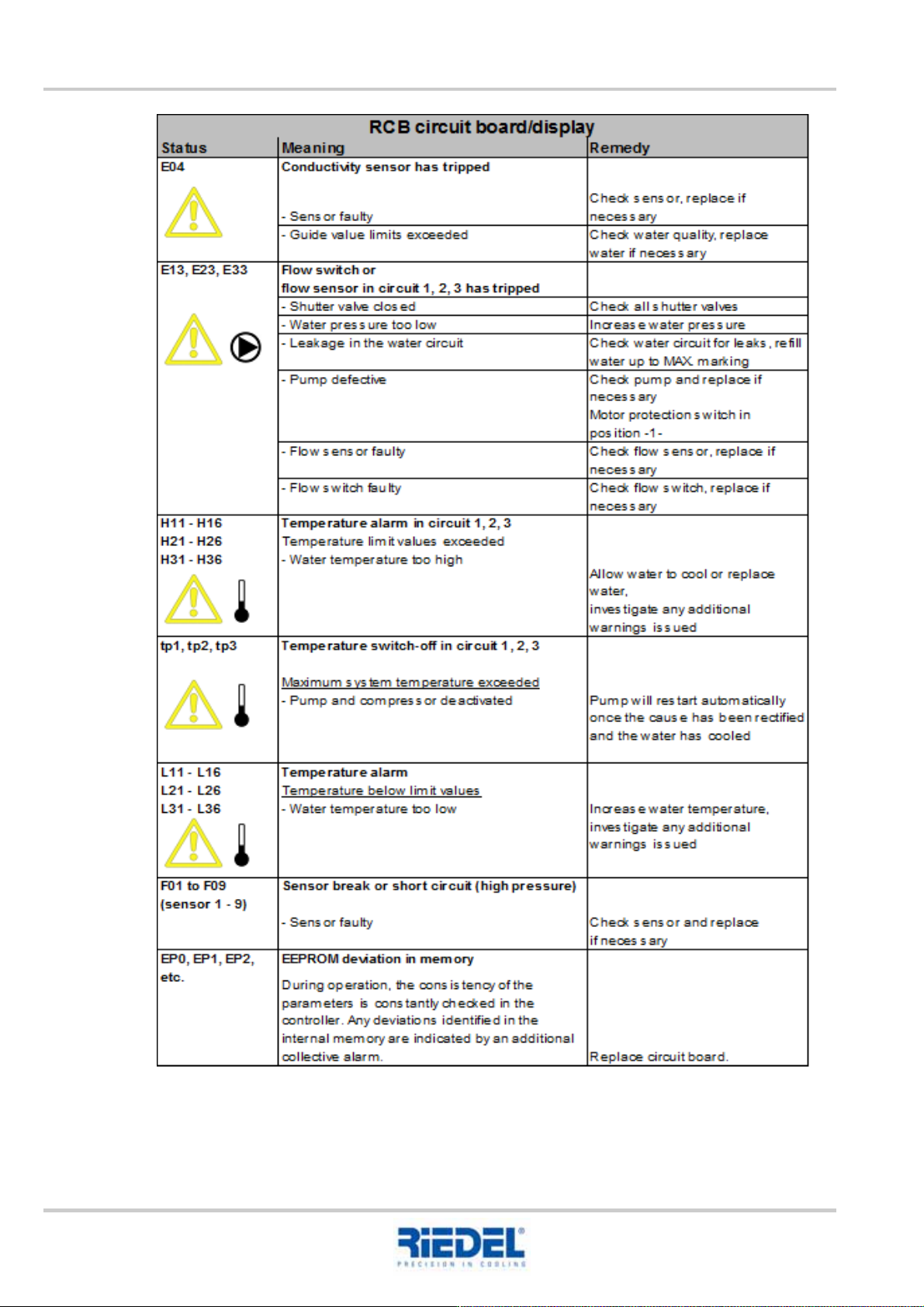
14. DIAGNOSIS OF UNPLANNED SWITCH OFFS ENGLISH Translation of the original
82
451820.66.03_EN
2020-05-05

Translation of the original ENGLISH 15. OPTIONS AND ACCESSORIES
451820.66.03_EN
2020-05-05
83
15. OPTIONS AND ACCESSORIES
15.1 Refrigerant circuit
15.1.1 Pressure gauge
The pressure gauge indicates the refrigerant pressure in the refrigerant circuit (high and low
pressure).
15.2 Water circuit
15.2.1 Pressure gauge
The pressure gauge displays the pressure of the water outlet or water inlet.
15.2.2 Start-up help for winter
The start-up help for winter prevents low-pressure faults in the case of low ambient temperatures
during the cooling start-up phase, until normal operating conditions have become established.
15.2.3 Overflow valve
The overflow valve guarantees the minimum flow in the water circuit.
In the pass-through and single-circuit systems, this protects the evaporator and pump. In the dual-
circuit system, the overflow valve protects the secondary pump.
The factory setting of the overflow valve is based on the technical specification or the customer-
specific system configuration.
Improper modifications or settings of the overflow valve can result in malfunction or damage to the
cooling unit or its components.
Necessary changes or pre-settings must only be made in consultation with RIEDEL after-sales
service, e.g. following modifications or adjustments to the cooling unit, the line length, the medium
etc. The assembly and operating instructions of the overflow valve must be observed. All work must
be performed by qualified personnel. An incorrectly adjusted overflow valve can lead to flow noise
and switch-offs.
When shutting down the cooling unit, following operation using water without glycol, the overflow
valve must be fully drained to prevent frost damage (during storage or transport).
15.2.4 Fixed bypass
The fixed bypass guarantees the minimum flow rate in the water circuit. In the pass-through and
single-circuit systems, this protects the evaporator and pump.
The fixed bypass is configured on a project-specific basis.
15.2.5 Dirt filter
If there is a risk of water contamination with solid particles with a diameter of > 1 mm during
operation, a dirt filter of appropriate mesh size should be used. Mount the dirt filter outside the
cooling unit while observing the flow direction.
Clean the dirt filter after commissioning and at regular intervals.
15. OPTIONS AND ACCESSORIES ENGLISH Translation of the original
84
451820.66.03_EN
2020-05-05
15.2.6 Fine filter
If there is a risk of water contamination with solid particles with a diameter of < 1 mm during
operation, a fine filter of appropriate mesh size should be used. Mount the fine filter outside the
cooling unit while observing the flow direction.
Clean the fine filter after commissioning and at regular intervals.
15.2.7 Check valves, solenoid valve
These valves are used with open systems and higher consumers.
Mount the valves outside the cooling unit while observing the flow direction.
15.2.8 Digital thermometer (single/dual-circuit system)
The thermometer records the water inlet temperature, which is displayed on the control and
operating unit.
15.2.9 Temperature limit values
The water temperatures in the water circuit are monitored by limit values and if the set limit values
are exceeded or fallen short of a collective fault is triggered via the control and operating unit.
15.2.10 Tank heating as freeze protection
The tank heating is used to heat the water in the tank. In the case of a low ambient temperature and
lacking process heat, (e.g. machine downtime), this prevents the water from freezing.
The circulating pump is activated by a thermostat when there is a risk of frost. The electric heating is
controlled by a thermostat with sensor in the water circuit.
This option is only effective if the cooling unit is supplied with electrical power according to
the specification and the control remains active.
The risk of frost damage resulting from a power failure is borne by the system operator.
15.2.11 Flow switch
The flow switch is installed in the water inlet pipe and switches the flow in the water circuit. The flow
switches off the cooling if the flow rate falls below the minimum value.
15.2.12 Insulation of the water pipes and pump(s)
At water temperatures < +12°C the water pipes and pump(s) are insulated.
This prevents the formation of condensate.