'操作说明 Hotflow THREE_26_zh.pdf - 第501页
10. ENVIRONMENT AL REQUIREMENTS ENGLISH T ranslation of the original 44 451820.66.03_EN 2020-05-05

Translation of the original ENGLISH 10. ENVIRONMENTAL REQUIREMENTS
451820.66.03_EN
2020-05-05
43
10. ENVIRONMENTAL REQUIREMENTS
During repair work on or decommissioning of the cooling unit, all environmental requirements
regarding recovery, recycling and disposal of materials and components should be observed in
accordance with EN 378.
The operator of the cooling unit is responsible for ensuring that materials and system
components which are no longer suitable for use are disposed of correctly.
Water containing additives must be disposed of in consultation with the responsible authorities at
regional level.
With regard to the
• Law for the prevention and remedying of environmental damage
(Environmental Damages Act – USchadG)
• Directive EC 35/2004 for environmental liability
• Law for the management of water resources (Water Resources Act – WHG)
• Ordinance on installations handling substances hazardous to water and on specialist
companies
• VAwS – Facilities Ordinance
the following applies:
General due care:
In relation to measures that could potentially impact a stretch of water, everyone is obligated to
apply the due care required under these circumstances to avoid a negative change in the properties
of the water.
Systems must be obtained and operated in such a way that substances hazardous to water cannot
escape unregulated. They must be sealed and suf ficiently resistant to expected mechanical, thermal
and chemical influences.
This can be done using:
Tanks/containers able to retain the volume of liquids hazardous to water that would otherwise
escape before suitable safety measures can be put in place (e.g. sealing off the leaking system part
or fixing the leak).
Including monitoring by automated fault indication systems in conjunction with permanently manned
premises (e.g. control room) or monitoring by means of regular inspections.
Recording of deviations from the intended operation as well as implementation of necessary
measures along with an alarm and action plan, which describes effective measures and precautions
for avoiding water pollution and has been coordinated with the relevant parties.
Single-walled, underground containers and pipework are not permitted.
Measures must therefore be implemented for the current project that prevent any escape of the
glycol-water mixture from the liquefier on the roof of the technology extension, the connecting
piping, heat exchanger station or the distribution system in the hall in the case of an accident or
emergency.

10. ENVIRONMENTAL REQUIREMENTS ENGLISH Translation of the original
44
451820.66.03_EN
2020-05-05
Translation of the original ENGLISH 11. OPERATION
451820.66.03_EN
2020-05-05
45
11. OPERATION
The cooling unit is switched on with the mains disconnecting device (main switch). This switch also
acts as the EMERGENCY STOP switch.
The cooling unit is ready for operation and the control and operating unit is now regulating the water
outlet temperature.
It is not possible to carry out commissioning when there is a signal pending denoting a water
shortage or dry run protection.
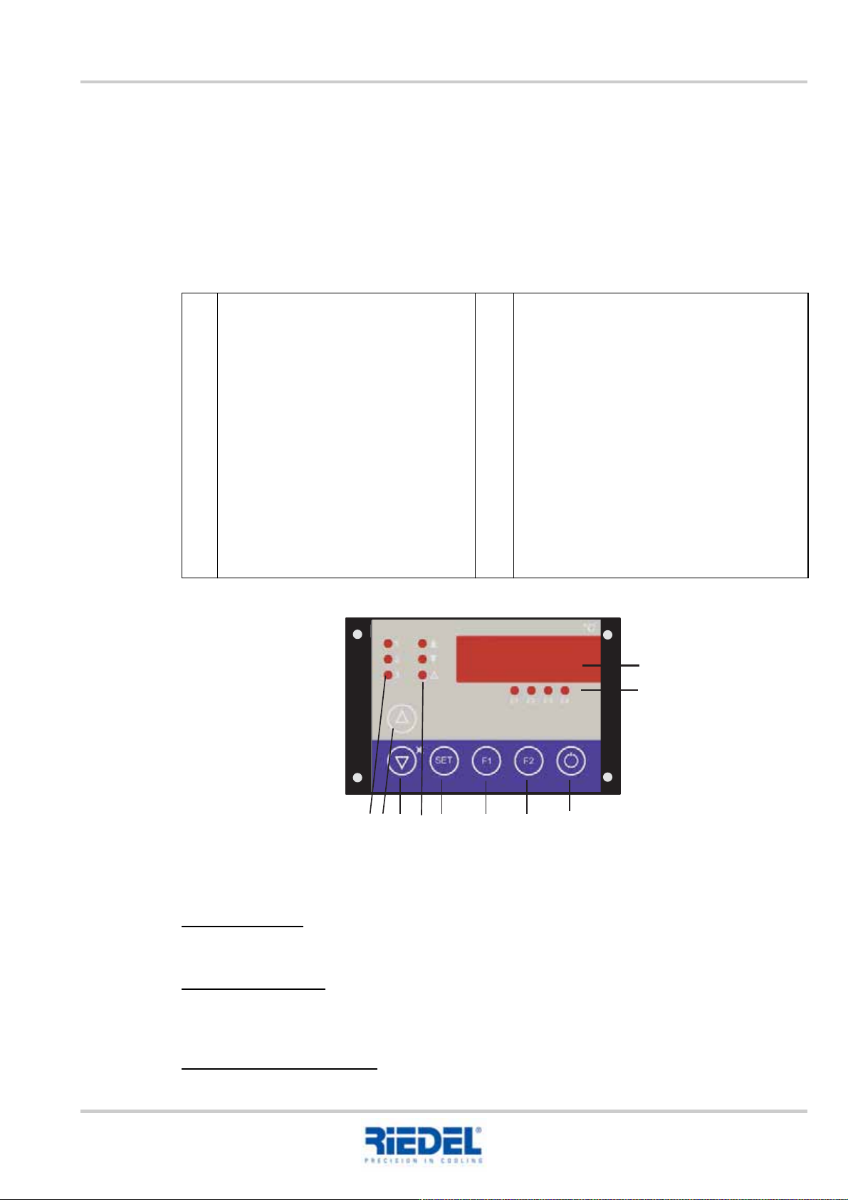
11.1 Control and operating unit ST 501
Control and operating unit ST 501
Actual values
Version with tank:
In the basic state, the flow temperature of the water circuit is shown in the display.
Version without tank:
In the basic state, the return temperature of the water circuit is shown in the display.
Press key F2 to display the flow temperature.
Adjusting the setpoint value:
To configure the setpoint value, press the SET key as well as the UP or DOWN key.
1
2
3
4
5
Display
Status displays
E1 Status – pump + water level
E2 Status – high pressure
E3 Status – low pressure
E4 Status – TC fan
Control stages
1 Pump on
2 Control stage 1 on
3 Control stage 2 on
UP key
Increase setpoint value or parameter
value
DOWN key
Decrease setpoint value or parameter
value
6
7
8
9
10
Alarm displays
"Up arrow" Fixed-setpoint regulation up for
differential regulation
"Down arrow" Fixed-setpoint regulation
down for differential regulation
"Alarm" Centralised fault indication
SET Calls the setpoint value or parameter
display
F1 key -> special function following parame-
ter release
F2 key -> special function following parame-
ter release
Stand by key
Controller on/off option
1
2
3
SET
E1
E2 E3
E4
F1
F2
°C
1
2
3 4 5 6 7 8 9 10