00198268-02_GS_SIPLACE-Pro-14.1-R17-1_EN.pdf - 第11页
Getting S tarted SIPLACE Pro 14.1 (R17-1) 2 Program Overview 05/2017 Edition 2.2 The User Interface 11 2.2.1 Menu Bar The menu bar cont ains the functions. Select the required m enu item to display the corr esponding fun…
2 Program Overview Getting Started SIPLACE Pro 14.1 (R17-1)
2.2 The User Interface 05/2017 Edition
10
2.2 The User Interface
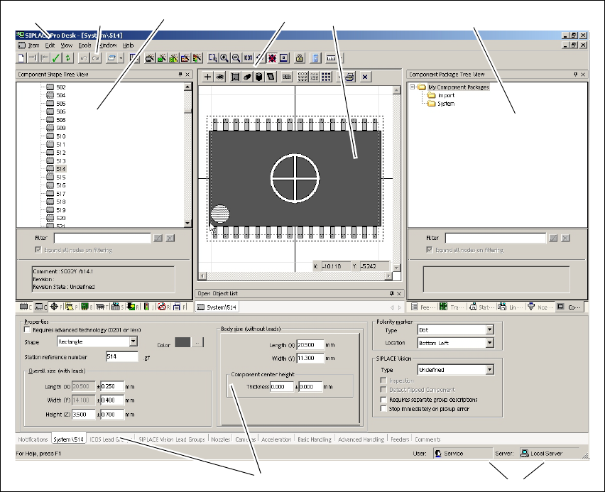
This chapter will help you to familiarize yourself with the SIPLACE Pro user interface. The user
interface is divided into the following areas. These contain all the functions and editors needed to
create a placement program with SIPLACE Pro. This example shows the user interface with the
opened Component Shape Editor. 2
2
Fig. 2 - 2 The user interface
Key
(1) Menu bar (2) Toolbar
(3) Tree view - product objects (4) Editor toolbar in window (may vary
between editors)
(5) View area/window (6) Tree view - Equipment objects
(7) Editor editing areas as tabs (may vary
between editors)
(8) Shows the current user name and the
server to which this desk is connected
123 45
7
6
8
Getting Started SIPLACE Pro 14.1 (R17-1) 2 Program Overview
05/2017 Edition 2.2 The User Interface
11
2.2.1 Menu Bar
The menu bar contains the functions. Select the required menu item to display the corresponding
functions. Frequently used functions can also be accessed from the toolbar or with key combina-
tions (shortcuts). 2
2
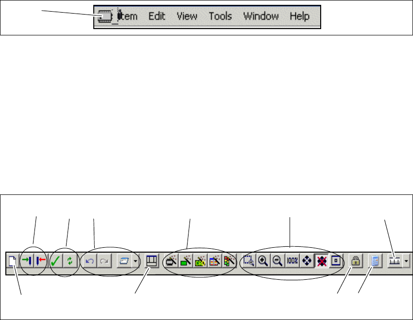
Fig. 2 - 3 Menu bar
Key
2.2.2 Toolbar
The toolbar contains the functions most frequently used. 2
These functions can be directly accessed with the individual icons. 2
2
Fig. 2 - 4 Toolbar
Key
(1) Icon for the active editor (e.g. component shape)
1
(1) Create new object (2) Save state, reset state
(3) Perform integrity check, refresh all editors (4) General functions (undo/redo, Report
Manager)
(5) Reset default layout for user interface (6) Wizards
(7) Zoom functions (8) Lock workplace
(9) Calculator (10) Set measurement unit
1
24
5
6
73
9
8
10
2 Program Overview Getting Started SIPLACE Pro 14.1 (R17-1)
2.2 The User Interface 05/2017 Edition
12
2.2.2.1 Zoom Functions
2
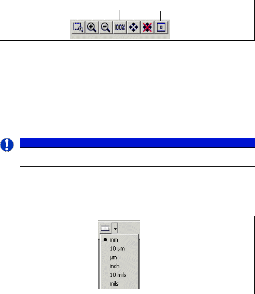
Fig. 2 - 5 Zoom function
Key
2
2.2.2.2 Setting the Measurement Unit
Set the required measurement unit. All measurements for the opened object will be adjusted to
this unit. 2
2
Fig. 2 - 6 Setting the measurement unit
(1) Box Zoom (2) Zoom In
(3) Zoom Out (4) One to One
(5) Zoom To Fit (switch on/off by drag & drop) (6) Switch on/off automatic zoom to fit option
when using Drag and Drop
(7) Center 2
Note
The zoom functions are only active when an object has been selected.
12 5364 7