00198268-02_GS_SIPLACE-Pro-14.1-R17-1_EN.pdf - 第30页
3 T utorial Getting S tarted SIPLACE Pro 14.1 (R17-1) 3.2 Exercise 1: Importing ASCII Centroid Data 05/2017 Edition 30 Result 3 The component shapes have b een assigned. There is no component shape available for the com-…
Getting Started SIPLACE Pro 14.1 (R17-1) 3 Tutorial
05/2017 Edition 3.2 Exercise 1: Importing ASCII Centroid Data
29
Result 3
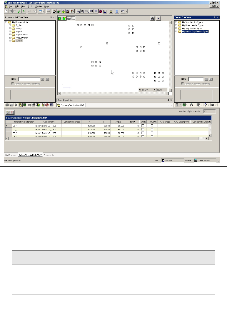
A placement list has been created. You now need to assign component shapes (see also section
3.2.2 on page 29). One of the components does not yet have a component shape assigned. This
needs to be created in Exercise 2: Creating a Component Shape. 3
3
Fig. 3 - 2 Result: "Placement list created" screen
3.2.2 Assigning Component Shapes to Components
Select the Component shapes tree view and open the
System directory.
Use the drag & drop function to assign the required component shapes to the placement list.
– Use the data in the following table to help you:
Component Component shape
MMELF 201
0805 103
SOT23 400
1206 105
3 Tutorial Getting Started SIPLACE Pro 14.1 (R17-1)
3.2 Exercise 1: Importing ASCII Centroid Data 05/2017 Edition
30
Result 3
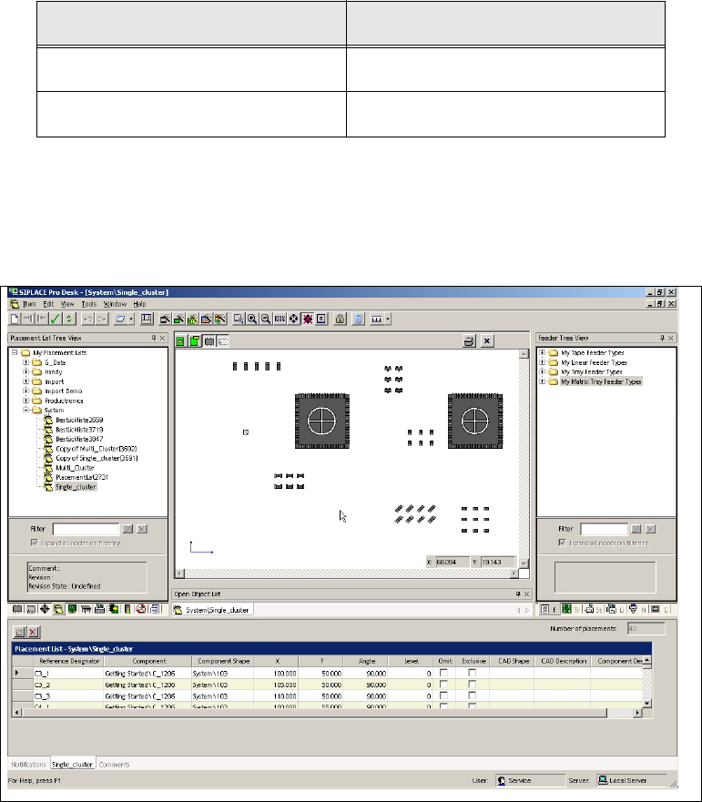
The component shapes have been assigned. There is no component shape available for the com-
ponent SO20L. This will need to be created in Exercise 2: Creating a Component Shape. 3
3
Fig. 3 - 3 Result: "Placement List created and Component Shapes assigned" screen
Close the placement list.
Create the directory My Placement Lists\Getting Started in the Saves As dialog box.
Save this placement list as Single_Cluster.
3
PLCC 68 704
SO20L You will create this in exercise 2.
Component Component shape
Getting Started SIPLACE Pro 14.1 (R17-1) 3 Tutorial
05/2017 Edition 3.3 Exercise 2: Creating a Component Shape
31
3.3 Exercise 2: Creating a Component Shape
Aim of exercise 3
A component shape will be created for the component SO20L and then assigned to this compo-
nent. 3
How to create a component shape 3
Open the Wizard with Tools => Component Shape Wizard... or by clicking on the icon.
In the Configure Component Shape - Step 1 of 4 dialog box, select the Integrated Circuits
tab.
Then select 2-Row Component Shape from the Select a Component Shape Type - Step 1 of
4 dialog box.
Click on Next.
In the Configure Component Shape – Step 2 von 4 dialog box, choose the lead type Gull
Wing.
Click on Next.
Select the option Overall width from the Configure Component Shape – Step 3 of 4 dialog box.
– Enter the following data for your component shape:
Click on Next.
Units mm
Body width 7.400
Length (X) 12.800
Pitch 1.270
Lead width 0.430
Lead length 1.400
Contact length 0.400
Height (Z) 2.500
Width (Y) 10.200 (will be preset)