00196351-06_UM_ACT_DE_EN.pdf - 第120页
ACT - Accurac y Check Tool / User Manual 09/2015 Edition 30 4.1.2 S cheduling the Boards ► Select a suiting pla cement program for your head configurat ion from t he pre - configured boards (with the aid of Table 4-1 or …

ACT - Accuracy Check Tool / User Manual 09/2015 Edition
29
4.1.1.2 Placement Program Overview for SIPLACE Pro ≥ 11.x
Station software version 706.02.SP1 Hotfix 2 or 707.1.SP1 Hotfix 2 or higher
Machine Head Camera Nozzle Placement program
X-/SX-/DX-series;
X-series S;
CAx
with SW 605.xx
1 x C&P20x
SST 23,
SST 41
1004 / 1014 /
4004
ACT_1xC&P20
(80 x Cerampad)
2 x C&P20x
ACT_2xC&P20
(2 x 80 x Cerampad)
4 x C&P20x
ACT_2xC&P20
(4 x 80 x Cerampad)
CAx with SW
≥707.1.SP1 Hotfix 2, or
706.02.SP1 Hotfix 2;
X-series S micron
≥708.0
1 x C&P20x
SST 41 1004 / 1014
ACT_1xC&P20_HighPrecision
3)
(80 x Cerampad)
2 x C&P20x
ACT_2xC&P20_HighPrecision
3)
(2 x 80 x Cerampad)
CAx,
X-series S micron
≥708.0
1 x CPP
(C&P mode)
SST 30 2004
ACT_1xC&P12_HighPrecision
3)
(96 x Cerampad)
2 x CPP (C&P mode)
ACT_2xC&P12_HighPrecision
3)
(2 x 96 x Cerampad)
X-/SX-/DX-/D-series;
X-series S;
E by SIPLACE
4)
1 x C&P12-DLM,
1 x CPP
(C&P mode)
SST 28,
SST 29,
SST 30,
SST 38
904 / 914;
2004 / 3004
ACT_1xC&P12
(96 x Cerampad)
2 x C&P12-DLM,
2 x CPP
(C&P mode)
ACT_2xC&P12
(2 x 96 x Cerampad)
D-/X-series and
CAx
with SW 605.xx;
E by SIPLACE
4)
C&P6
SST 29,
SST 30
920 / 3020
ACT_CC02-05
(48 x CC02-05)
X-/SX-/DX-/D-series;
X-series S;
E by SIPLACE
4)
TH-IC,
P&P-IC,
CPP (P&P mode)
SST 33,
SST 36
518 / 2057
ACT_CC02-05_PP
2)
(48 x CC02-05)
X-/SX-/DX-/D-series;
X-series S;
TH-IC,
P&P-IC,
CPP
(P&P mode)
SST 33,
SST 36
518 / 2057
ACT_CC02-05_CPP_TH
5)
(48 x CC02-05)
X-/SX-/DX-/D-series;
X-series S;
E by SIPLACE
4)
TH-IC,
P&P-IC
SST 25 518
ACT_CC02-05_FC
1)
(48 x CC02-05)
E by SIPLACE
4)
1 x C&P14
SST 23,
SST 41
4004
ACT_1xC&P14
(112 x Cerampad)
Table 4-2: Assignment of machine, board, head as of SIPLACE Pro 11.x
1)
As of software SIPLACE Pro 11.x with station software version 706.02.SP1 Hotfix 2 or 707.1.SP1 Hotfix 2 or higher,
the CC02-05 component (with QFP structure) is used for the SST 25 camera (Flip-Chip camera).
The CC07-500 glass component (with BGA structure) is not supported anymore.
If the CC07-500 component is already available and still to be used for measuring the SST 25 camera, the
corresponding board with its component and component shape data and the tables can be selectively imported from
the *.sipro files of the SIPLACE Pro 9 version. This data can be obtained from the Software License Portal or via the
hotline.
2)
As of software SIPLACE Pro 11.x with station software version 706.02.SP1 Hotfix 2 or 707.1.SP1 Hotfix 2 or higher.
From this version, a separate board description is available for all Pick & Place heads in which the CPP head has now
been integrated for the P&P mode.
3)
For machines requiring higher precision, such as CA machines and X S Micron, separate high precision programs with
high precision Cerampads are available for measuring the C&P20 heads. As of the software versions mentioned
above, it is possible to enable a Precision parameter in the component shape description.
4)
Machine type E by SIPLACE, as of station software version 708.0.
5)
For compatibility with older station software versions.
If SIPLACE Pro has been updated without updating the station software, the machine verification of CPP heads in P&P
mode can be performed anyway with this program.
ACT - Accuracy Check Tool / User Manual 09/2015 Edition
30
4.1.2 Scheduling the Boards
► Select a suiting placement program for your head configuration from the pre-configured boards
(with the aid of Table 4-1 or Table 4-2).
► Specify a job (recipe) in SIPLACE Pro Line Control and send it to the line (download).
NOTICE
Placement machines with dual conveyors
When using a dual conveyor, the ACT should be run with both conveyor lanes.
4.1.2.1 Troubleshooting: Accessibility for Various Machine / Head Configurations
SIPLACE SX4 and DX4 machines:
NOTICE
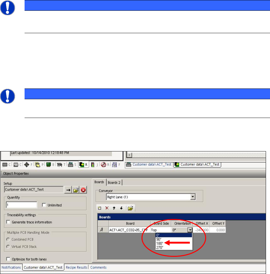
In order to access the fiducials, the ACT measuring plate has to be placed rotated by
180° in SIPLACE SX4 and DX4 machines.
Thus, if an ACT placement program is defined for a SIPLACE SX4 or DX4 machine, the orientation
(position) of the board has to be adapted to 180° in the created recipe.
Figure 4-1: Rotating board orientation by 180°on SX4, DX4
ACT - Accuracy Check Tool / User Manual 09/2015 Edition
31
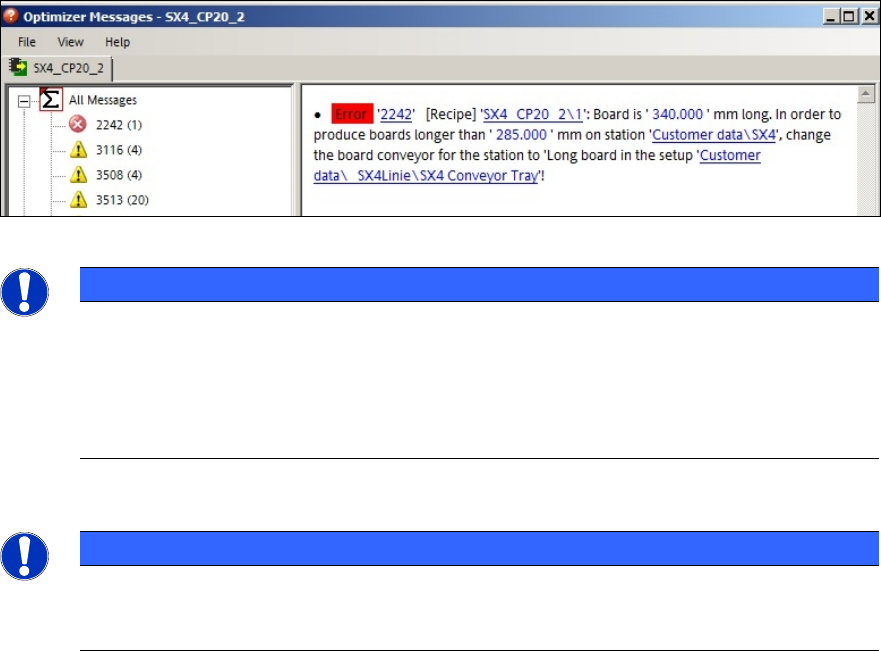
If this adaption of the board orientation is not performed, the following error message (example) is
already displayed on the SIPLACE Pro Line Control GUI during specification:
Figure 4-2: Example: Error message due to unavailable ink spots
NOTICE
Due to the problems of accessing the fiducials described above, please observe:
If the ACT has to be measured on a machine of the SX-, DX-, or X-series, in front of
which one or more SIPLACE SX4- or DX4-stations are arranged in a line, the Pass-
through function has to be activated on all machines in front of the measuring machine
that require another board orientation (0°/180°). Otherwise errors will occur when trying
to access the fiducials.
Twin Head – statistical reliability:
NOTICE
► Pay attention to the number of placed components per segment when measuring a
Twin Head, to ensure the statistical reliability of the measurement result.
At least 20 components per segment should be placed!
When setting up the tray with the glass components, pickup problems may occur for one segment
at some machine types because the components cannot be accessed.
► Pay attention to the tray positioning at the component table or in the WPC.
Variants:
► Make sure that the components can be accessed by both segments in X direction when
positioning the tray at the component table.
When the two front rows have been run empty:
► Stop the machine.
► Refill the components in the front rows.
► Reset the filling level to "Full".
This also applies when setting up the tray in the WPC. The components have to be refilled in
the WPC too (e.g. WPC at the SX1/2 machine) to ensure that a sufficient number of
components can be picked up by both Twin segments.
► If possible, use the Tray in Transport for ACT option. Thus, the accessibility in Y direction is
ensured.