00196351-06_UM_ACT_DE_EN.pdf - 第156页
ACT - Accurac y Check Tool / User Manual 09/2015 Edition 66 Example of measurement oper ation with the ceramic com ponents Cerampads: Figure 4-46: Example of meas urement window with Cerampads Example of measurement oper…
ACT - Accuracy Check Tool / User Manual 09/2015 Edition
65
The machine automatically switches to standalone mode.
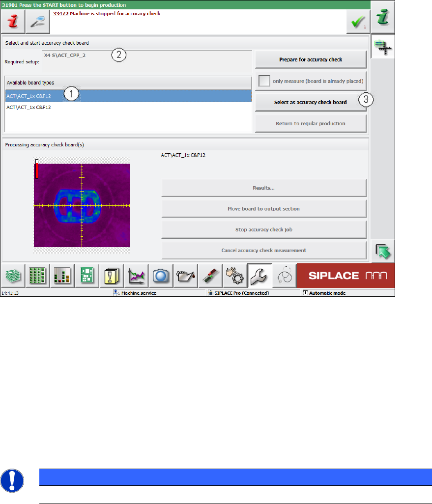
Figure 4-45: Selecting board
► Select the required board (1). The board most recently specified is always at the top of the list.
When you have selected a board, the corresponding setup appears at this point (2).
► Confirm the selection of the board and click the Select as accuracy-check-board button (3).
► Press the Start key before you insert the board (otherwise it will not be placed but immediately
be moved to the output section).
► Push the board into the input section in order to start placement (see also section 4.2.2 and
section 4.2.4.2).
The board gets placed and then the measurement starts automatically.
NOTICE
The machine should not be operated during the measurement!
A dialog box opens in which the current measurement operation is displayed.
The fiducials which are currently being measured will be displayed.
ACT - Accuracy Check Tool / User Manual 09/2015 Edition
66
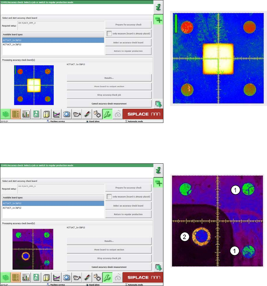
Example of measurement operation with the ceramic components Cerampads:
Figure 4-46: Example of measurement window with Cerampads
Example of measurement operation with glass components:
Figure 4-47: View of measurement window with glass components (pseudo color view)
Key:
(1) Fiducials on the ACT plate
(2) Fiducials on the glass component
ACT - Accuracy Check Tool / User Manual 09/2015 Edition
67
4.2.6.1 Measurement Evaluation and Measurement Data
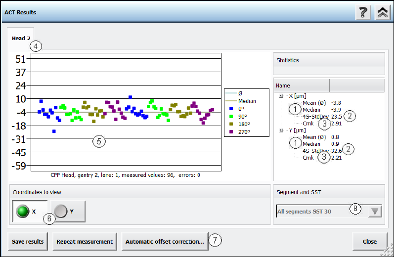
The measurement results are then displayed as follows:
Figure 4-48: ACT measurement results
Key:
(1) Median value, can be changed with the Automatic offset correction…
button.
(2) Standard deviation at 4 sigma.
(3) Cmk: must be 4 Sigma >1.33 and 3 Sigma > 1.0.
(4) Here you can switch between the heads (gantries).
(5) Measurement details.
(6) Switches the measurement result.
(7) Here you can correct the measured offset values.
(8) If the head in use is a Twin Head, you can select the individual
segments here, if both segments have placed components on a plate.
X
Displays the offset values in the X direction.
Y
Displays the offset values in the Y direction.
Angle (not for Cerampads)
Displays the offset values for the placement angle.