00196351-06_UM_ACT_DE_EN.pdf - 第144页
ACT - Accurac y Check Tool / User Manual 09/2015 Edition 54 Figure 4-32: Dialog box after setti ng ACT mode. Displ ay: ACT icon The Leiterpl atteneingab e ( Enter PCB ) dialog b ox is opened ( Fig ure 4- 33 ). ► Select t…
ACT - Accuracy Check Tool / User Manual 09/2015 Edition
53
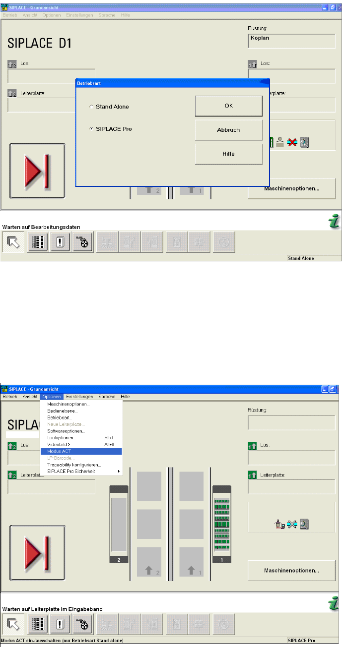
Figure 4-30: Dialog box operating mode switchover to SIPLACE Pro at the station (example SIPLACE D1)
► Press the START button on the machine.
The reference run is carried out.
► Send the recipe / job to the station with the relevant setup and the ACT placement program.
► From the Optionen (Options) menu, select Modus ACT (ACT mode).
The ACT dialog box opens and the machine will automatically switch to Stand Alone mode.
Figure 4-31: Basic view of user interface for SC program (example SIPLACE D1)
After setting ACT mode, an icon will be displayed for ACT.
ACT - Accuracy Check Tool / User Manual 09/2015 Edition
54
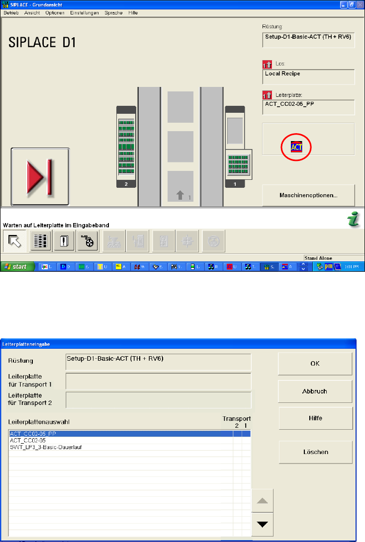
Figure 4-32: Dialog box after setting ACT mode. Display: ACT icon
The Leiterplatteneingabe (Enter PCB) dialog box is opened (Figure 4-33).
► Select the ACT board.
Figure 4-33: Dialog box: Enter PCB (example SIPLACE D1)
The Leiterplatteneingabe (Enter PCB) dialog box is opened (Figure 4-34).
► Select the ACT board.
► Select the conveyor lane.
► Confirm your entry with OK.
ACT - Accuracy Check Tool / User Manual 09/2015 Edition
55
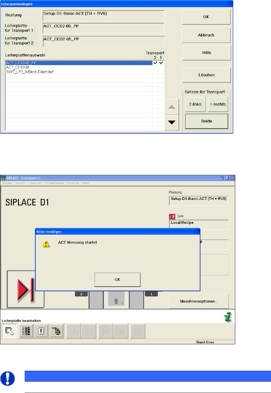
Figure 4-34: Dialog box: Enter PCB (example SIPLACE D1)
► Now insert the board into the input section (see also section 4.2.2).
The board gets placed and then the measurement starts automatically.
Figure 4-35: Message for ACT measurement (example SIPLACE D1)
NOTICE
The machine should not be operated during the measurement!
A dialog box opens in which the current measurement operation is displayed. The fiducials that are
currently being measured are displayed.