00193802-01.pdf - 第110页
4 Setting up t he placement system User Manual S IPLACE CF 4.1 Transport configuration and infrastructure Software version S R.101.xx 06/2003 US Edition 110 The standard P CB conv eyor hei ght is 83 0 mm ± 15 mm. The sta…
User Manual SIPLACE CF 4 Setting up the placement system
Software version SR.101.xx 06/2003 US Edition 4.1 Transport configuration and infrastructure
109
4 Setting up the placement system
4.1 Transport configuration and infrastructure
4
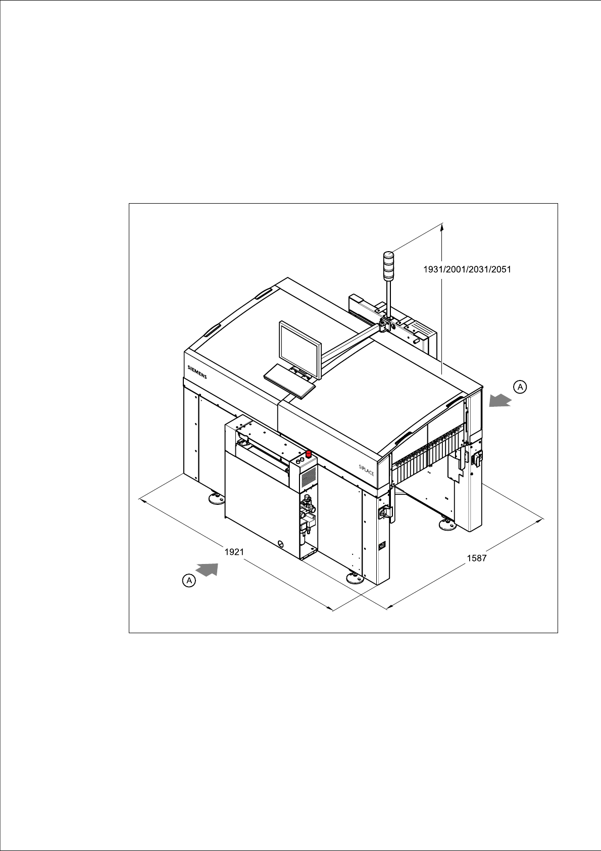
Fig. 4.1 - 1 Dimensions of the placement system during transportation and setting
up in millimeters
4
(A) Points for attaching the fork-lift truck (fork length 1600 mm)
(1) Input conveyor
(2) Output conveyor

4 Setting up the placement system User Manual SIPLACE CF
4.1 Transport configuration and infrastructure Software version SR.101.xx 06/2003 US Edition
110
The standard PCB conveyor height is 830 mm ± 15 mm. The standard overall height of the
machine is 1931 mm. For a PCB conveyor height of 950 mm (SMEMA option), this gives an
overall height of 2051 mm.
4.1.1 Transport configuration
The following components are not installed when the placement system is delivered from the fac-
tory:
– keyboard
–monitor
– indicator lamps
– Component trolley
– Component barcode reader
4.1.2 Safety instructions
WARNING
Æ The applicable accident prevention regulations concerning the transportation of heavy goods
must be followed.
Æ In particular, you should wear safety boots to minimize the risk of crushing your feet.
Æ When you are transporting the machine, make sure that all the feet are clear of the floor. If they
are not clear, the feet will drag along the floor and bump into obstacles. This could damage the
machine foot thread in the machine frame.
Æ Attach the pallet jack only at the points identified by (A) in Fig. 4.1 - 1).
4.1.3 Means of transport
Use a pallet jack with the following specification to carry the machine:
Fork length: min. 1800 mm
Carrying power: min. 2000 kg
Clear width between forks: min. 350 mm 4

User Manual SIPLACE CF 4 Setting up the placement system
Software version SR.101.xx 06/2003 US Edition 4.1 Transport configuration and infrastructure
111
4.1.4 Compressed air supply
4.1.4.1 Compressed air specification
The compressed air supply should conform to the following specification:
4
4
4.1.4.2 Checking the compressed air supply
Check that the compressed air supply conforms to the prescribed machine specifications.
PLEASE NOTE:
The document entitled "Network configuration (electrical and compressed air) for SMD systems
on the customer's premises", part no. 00191409-xx, describes the action that can be taken to
meet the required specifications. 4
Æ Record the compressed air characteristics at the installation location.
p
min
0.55 MPa = 5,5 bar
p
max
1.0 MPa = 10 bar
Connection 1/2"
Compressed air consumption 400 l/min.
Particle size 0.1 µm
Particle density 0.1 mg/m³
Maximum oil content (class 1) Particle density 0.01 mg/m³
Pressure dewpoint (class 4) Dewpoint + 3°