00193802-01.pdf - 第95页
User Manual SIPLAC E CF 3 Technical data Software version SR.101.xx 06/2003 US Edition 3.10 Vision modules 95 3.10 V isio n mod ules 3.10 .1 Desc riptio n Each placemen t system ha s – one c omponent v ision m odule on t…

3 Technical data User Manual SIPLACE CF
3.9 Placement heads Software version SR.101.xx 06/2003 US Edition
94
3.9.2.2 Description of the Pick&Place head
The Pick& Place head works on the Pick&Place principle. According to this principle, a compo-
nent is picked up by the nozzle with the aid of a vacuum. It is then optically centered by the fine-
pitch vision module, turned in the placement angle and placed on the PCB with high precision.
The Pick&Place head offers particularly high angular accuracy.
3.9.2.3 Technical data - Pick&Place head
3
Range of components PLCC, LCCC, QFP, SO, BGA, flip-chip,
components with connectors up to 55 mm x 55 mm
(J leads and gull-wings, balls, bumps)
Component specification
Max. height Component height ≤ 13.5 mm - PCB thickness
- PCB warpage
Option:
Component height ≤ 20 mm - PCB thickness
- PCB warpage
Min. lead pitch 0.4 mm
Min. bump pitch 0.56 mm
Min. ball/bump diameter 0.32 mm
Min. dimensions 1.6 mm x 0.8 mm
Max. dimensions 55 mm x 55 mm (92 mm edge length available upon
request)
Max. weight 25 g
Programmable placement force 1 - 10 N
Component centering Fine pitch camera
up to 32 mm x 32 mm with single measurement
up to 55 mm x 55 mm with quadruple measurement
Max. placement rate 1,800 comp/h
Nozzle types 4xx, 5 standard nozzles with nozzle changer
Angular accuracy ± 0.07° / 4 sigma
Placement accuracy ± 50 µm/4 σ
User Manual SIPLACE CF 3 Technical data
Software version SR.101.xx 06/2003 US Edition 3.10 Vision modules
95
3.10 Vision modules
3.10.1 Description
Each placement system has
– one component vision module on the 6-segment Collect&Place head,
– one fine pitch vision camera on the machine base and
– one PCB vision module on the underside of the X axis gantry.
The vision analysis unit is located in the control unit for the placement system. The component
vision module is used to determine:
– the precise position of the components at the nozzle and
– the geometry of the package form.
The PCB vision module uses fiducials on the PCBs to determine:
– the position of the PCB,
– its rotation angle
– and the PCB skew.
The PCB vision module also uses fiducials on the feeders to determine the exact pick-up position
of components. This is particularly important for small components.
3 Technical data User Manual SIPLACE CF
3.10 Vision modules Software version SR.101.xx 06/2003 US Edition
96
3.10.2 Component camera (standard camera) on the 6-segment Collect&Place
head
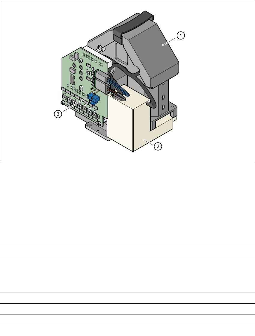
3.10.2.1 Structure
3
Fig. 3.10 - 1 Component camera (standard camera) on the 6-segment Collect&Place head
3
(1) Component camera, lens and illumination
(2) Camera amplifier
(3) Illumination control
3.10.2.2 Technical data
3
Max. component dimensions 0.6 mm x 0.3 mm to 18.7 mm x 18.7 mm
Range of components 0201 to PLCC44
including BGA, µBGA, flip-chip, TSOP, QFP
PLCC, SO to SO32, DRAM
Min. lead pitch 0.5 mm
Min. bump pitch 0.35 mm
Min. ball/bump diameter 0.2 mm
Field of vision 24 mm x 24 mm
Method of illumination Front-lighting (3 levels, programable as required)