00193802-01.pdf - 第76页
3 Technical data User Manual SIP LACE CF 3.5 Dimensions and weight of the placem ent machine Software version S R.101.xx 06/2003 US Edition 76 3.5.2 The placem ent system’ s center of gravit y 3 Fig. 3.5 - 2 The plac eme…
User Manual SIPLACE CF 3 Technical data
Software version SR.101.xx 06/2003 US Edition 3.5 Dimensions and weight of the placement machine
75
3.5 Dimensions and weight of the placement machine
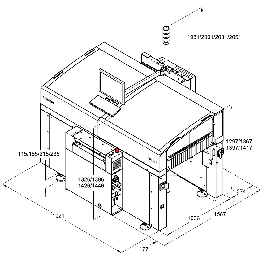
3.5.1 Dimensions of the placement machine
3
Fig. 3.5 - 1 Dimensions of the placement system in millimeters
3 Technical data User Manual SIPLACE CF
3.5 Dimensions and weight of the placement machine Software version SR.101.xx 06/2003 US Edition
76
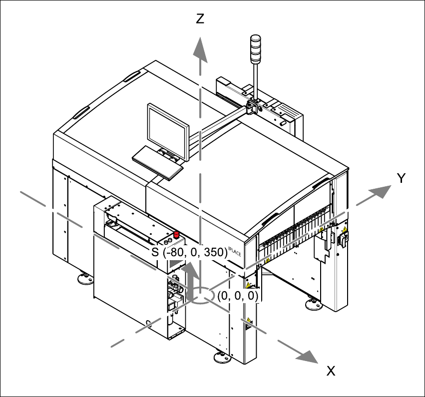
3.5.2 The placement system’s center of gravity
3
Fig. 3.5 - 2 The placement system’s center of gravity
3
X coordinate - 80 mm
Y coordinate 0 mm
Z coordinate 350 mm high
T PCB transport direction
These center of gravity coordinates relate to placement systems with a PCB transport height of
830 mm.
User Manual SIPLACE CF 3 Technical data
Software version SR.101.xx 06/2003 US Edition 3.5 Dimensions and weight of the placement machine
77
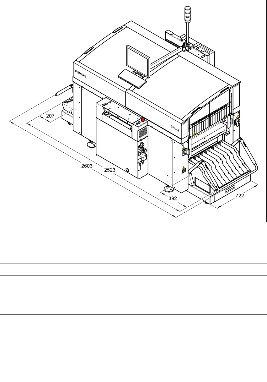
3.5.3 Dimensions of the placement machine with component trolley
3
Fig. 3.5 - 3 Dimensions of the placement machine with component trolley in millimeters
3.5.4 Technical data - dimensions, weight of the placement system
3
Length 1587 mm including conveyor belts
Width 1921 mm
2603 mm with component trolley
Height with warning lamp 1931 mm (standard height) /
2001 mm / 2031 mm/ 2051 mm SMEMA
Ground clearance 115 mm (standard height) /
185 mm / 215 mm/ 235 mm SMEMA
Weight of basic module 1500 kg
Weight fully equipped Approx. 2000 kg
Admissible load per unit area on foundation 1000 kg/m² min.
Load per unit area on mounting feet 4.42 kg/cm²