00193802-01.pdf - 第170页
6 Component handling User Manual S IPLACE CF 6.6 Waffle-pack changer Software version S R.101.xx 06/2003 US Edition 170 Fig. 6.6 - 6 Setting up the WPC 6 (1) Us ing UP/DOWN Allen key (2) Clamping s crew (3) S troke (4) D…

User Manual SIPLACE CF 6 Component handling
Software version SR.101.xx 06/2003 US Edition 6.6 Waffle-pack changer
169
6.6.6 Safety equipment
Emergency stop button
The entire system, i.e. SIPLACE CF and waffle-pack changer, is stopped immediately.
You can then either continue or cancel placement. Check whether there are any incomplete
PCBs remaining.
Safety doors
When the safety doors are opened, the power to the waffle-pack changer is switched off and the
sequence of waffle-pack changer functions stops. It resumes its functions when the safety doors
are closed.
CAUTION 6
Do not open the safety doors of the waffle-pack changer while it is picking up a component. 6
6.6.7 Installing the waffle-pack changer
Æ Before you push the waffle-pack changer into the placement machine, remove the top part of
the fine pitch camera.
CAUTION DANGER OF TIPPING 6
The waffle-pack changer runs on wheels. However, these are only suitable for short distances,
i.e. for docking in and out of the placement machine. Given the danger of tipping, use a suitable
pallet jack for longer distances (part no. 00123141-01). 6
Æ Carefully push the WPC into location 1 on the machine. The docking pins of the WPC must
protrude over the docking grooves in the SIPLACE CF.
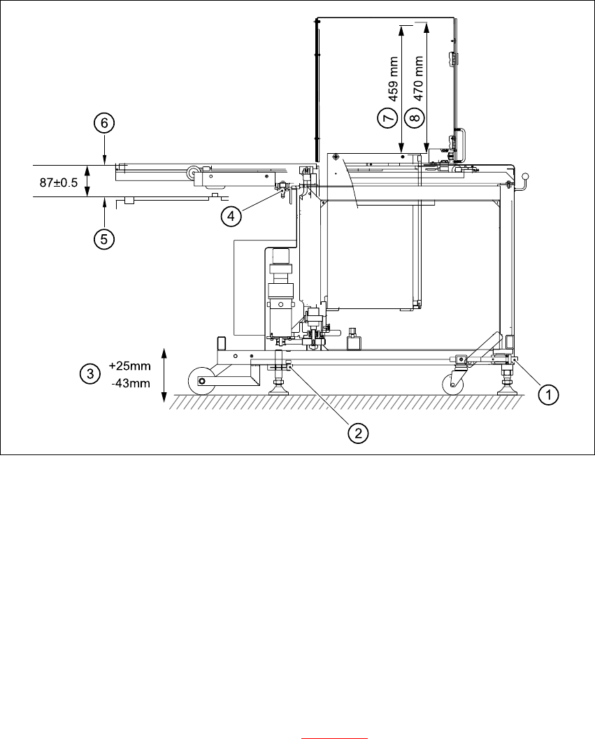
Æ Check the measurement (87 +/- 0.5 mm) from the bottom edge of the magazine carrier to the
top edge of the component feeder table (see Fig. 6.6 - 6
).
6 Component handling User Manual SIPLACE CF
6.6 Waffle-pack changer Software version SR.101.xx 06/2003 US Edition
170
Fig. 6.6 - 6 Setting up the WPC
6
(1) Using UP/DOWN Allen key
(2) Clamping screw
(3) Stroke
(4) Docking pin
(5) Top edge of component feeder table magnetic rail
(6) Bottom edge of magazine carrier
(7) Nominal travel (459 mm)
(8) Refill position (470mm)
6
Æ Loosen the clamping screws on the feet (see Fig. 6.6 - 6) and use a 10 mm ball-tip Allen key
to turn the WPC down until docking pin engages. At the same time, align the WPC using the
machine's integral spirit level.
Æ Tighten the clamping screws and check the machine spirit level again.
Æ Place the top part of the camera on the component vision module once more.

User Manual SIPLACE CF 6 Component handling
Software version SR.101.xx 06/2003 US Edition 6.6 Waffle-pack changer
171
6.6.8 Technical data
6
6
Waffle-pack changer
Length Approx. 1475 mm
Width Approx. 620 mm
Height Approx. 1355 mm
Weight Approx. 240 kg
Vertical stroke 470mm
Horizontal stroke 730mm
Spacing 17mm
Storage capacity 28 magazine carriers for holding waffle-pack
trays
Magazine carriers 260 mm x 360 mm
Max. weight of the storage unit 50 kg
Floor loading < 25N/cm²
Max. magazine size 240 mm x 340 mm
Magazine height 15 mm, including component
Max. number of component types 200 per waffle-pack changer
Changeover time (magazine/magazine) ≤ 3 sec.