00193802-01.pdf - 第126页
5 Operator, Line engineer, Service engineer User Manual SIPLACE CF 5.6 Changing the f eeders Software version SR.101.xx 06/2003 US Edition 126 Æ Check that t he divid ing plat es in th e tape con tainer are insert ed cor…

User Manual SIPLACE CF 5 Operator, Line engineer, Service engineer
Software version SR.101.xx 06/2003 US Edition 5.5 Preliminary set-up of the placement station
125
5.5 Preliminary set-up of the placement station
Carry out the following steps to complete the preliminary set-up of the placement station.
Æ Remove the tapes from the feeders and vacuum the surfaces of the modules and the area
around the tape guide clean with the vacuum cleaner.
Æ Empty the waste tape container (see item 3 in Fig. 5.4 - 2).
Æ Clean the supporting surfaces of the feeders with a cloth moistened with alcohol.
Æ Apply a small amount of WD40 corrosion protection to the supporting surfaces with a lint-free
cloth.
Æ Use a vacuum cleaner or use a brush with short bristles
to remove loose components from the component feeder tables.
CAUTION
Avoid removing components from the magnetic rail of the component table with your fingers.
You may hurt yourself with tiny splinters of metal. 5
NOTE
The compressed air distributor rail on the component table is used to connect the bulk case
feeders. This rail runs parallel to the PCB transport and has nozzles with the openings on
the top. Make sure that the nozzles do not get dirty or come into contact with oil or grease.
Grease, oil and dirt can cause malfunctions in the feeder or may cause the components in
the feeder to become unusable! 5
Æ Check the surface of the magnetic rail for irregularities or damage and smoothen with an oil-
stone when necessary.
Æ Clean the magnetic rail with a cloth moistened with alcohol.
Æ Apply a small amount of WD40 corrosion protection to the magnetic rail with a lint-free cloth.
Æ Clean the supporting surfaces of the component feeder tables with a cloth moistened with al-
cohol, and then apply a small amount of WD40 corrosion protection with a lint-free cloth.
Æ Clean the tape container with a vacuum cleaner.
Æ Make sure that the feeders are divided up correctly.
Æ Are all the plugs of the feeder plugged in to the correct location?
Æ Make sure that the spacing in the tape transport of the feeder is correct.
Æ Shorten the used tape on the front of the feeder to a length of 1 cm.
5 Operator, Line engineer, Service engineer User Manual SIPLACE CF
5.6 Changing the feeders Software version SR.101.xx 06/2003 US Edition
126
Æ Check that the dividing plates in the tape container are inserted correctly (see item 5 in Fig. 5.4
- 2).
Æ Check the diameter of the component tape reels and insert a spindle for large reels.
Æ Splice short tape ends together.
The personnel maintaining the preliminary set-up area is to have access to the same equipment
as the machine operators. You will find a list of such equipment in section 5.2
.
NOTE
If the equipment is defective, then the machine operator is to inform the personnel in the prelim-
inary set-up area verbally or in writing. 5
5.6 Changing the feeders
Æ Handle the feeders carefully when you insert them into or remove them from the component
feeder table. Do not allow the supporting surfaces of the feeders to bang against the edges of
the component feeder table.
Æ Vacuum the supporting surfaces of the feeders and clean the surface of the component feeder
table when necessary according to the instructions in the Preventive Maintenance Manual.
RISK OF INJURY
Avoid removing components from the magnetic rail of the component table with your fingers.
You may hurt yourself with tiny splinters of metal. 5
Æ Remove loose components with a short-bristled brush.
User Manual SIPLACE CF 5 Operator, Line engineer, Service engineer
Software version SR.101.xx 06/2003 US Edition 5.7 Avoiding track errors
127
5.7 Avoiding track errors
5.7.1 General
Æ Make sure that the areas around the feeders are clean and that there are no loose components
in the feeder area or under the feeders.
Æ Ensure that the supporting surfaces of the feeders, and particularly the magnetic rails of the
component feeder tables, are clean and level.
Æ Refill promptly with components.
Æ Splice the tapes early. This generally means that you are to prepare the splicing material when
there is still approximately 1.5 m of tape on the reel.
Æ Handle the feeders carefully when you insert them into or remove them from the component
feeder table as these are high-precision devices.
Æ Close the flaps of the feeders because they can be easily damaged when open.
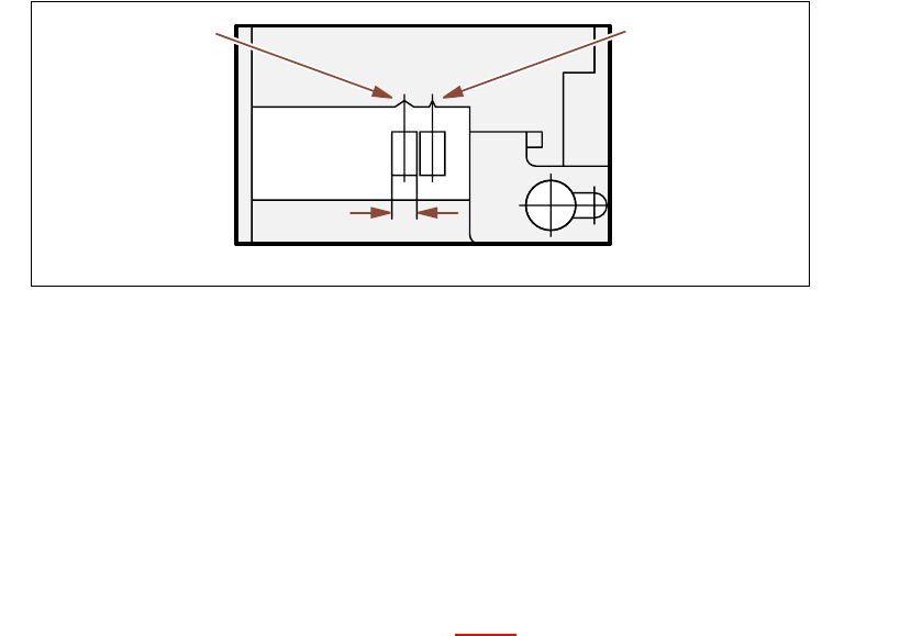
Æ Check that the pick-up position for components in the S feeders has been correctly set (see
example below).
Example for 8mm S feeders 5
Fig. 5.7 - 1 Pick-up position for components > 3 mm and </= 3 mm
Æ Check to see if all the plugs of the feeders are plugged in to the correct sockets.
5.7.2 ... on the 8 mm S tape feeder
Æ NEVER open the cover flap without first releasing the tension of the cover foil remover.
Æ Insert the tape material over the spring into the tape feeder.
5.7.3 ... on the tape container
Æ Insert the dividing plates correctly (see Fig. 5.4 - 2).
Æ Use spindles for large tape reels.
Component pick-
up position
> 3 mm
Component pick-
up position
≤ 3 mm
Width