00193802-01.pdf - 第179页
User Manual SIPLACE CF Index 06/2003 US Edition 179 Index Numerals 12 mm S feed er for capac itors based on powdered metal, m odel E model C/ D 144 mode l E 145 12/16 mm S feed er 143 24/32 mm S feed er 146 3 x 8 mm S fe…
7 Station extensions User Manual SIPLACE CF
7.1 Nozzle changer for the Pick&Place head Software version SR.101.xx 06/2003 US Edition
178
7.1.4 Notes on operation and maintenance
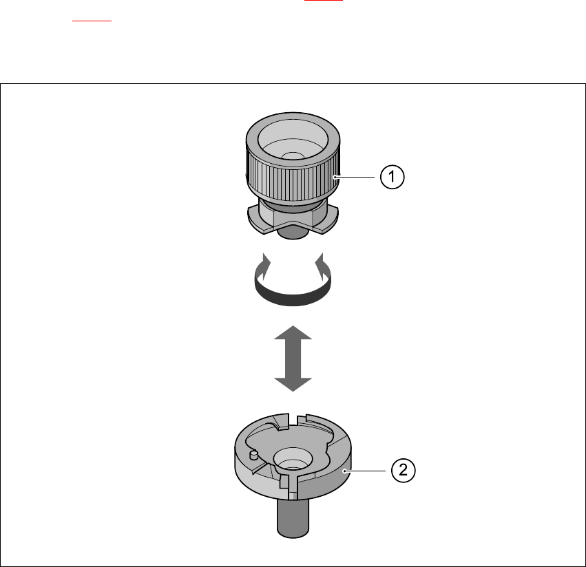
Æ Use the nozzle removal tool (see item 1 in Fig. 7.1 - 3) to insert and change the nozzles (item
2 in Fig. 7.1 - 3
).
Æ Clean the nozzle changer as described in the preventive maintenance instructions.
7
Fig. 7.1 - 3 Remove nozzle from the nozzle changer

User Manual SIPLACE CF Index
06/2003 US Edition
179
Index
Numerals
12 mm S feeder for capacitors based on powdered
metal, model E
model C/D
144
model E
145
12/16 mm S feeder
143
24/32 mm S feeder
146
3 x 8 mm S feeder
141
3x8mm S feeder for 0201/0402 components
142
44 mm S feeder
147
56 mm S feeder
148
6-segment Collect&Place head
67, 70, 90
angular accuracy
70
placement accuracy
70
6-segment Collect&Place head with standard com-
ponent camera
angular accuracy
92
component camera
90
component specifications
92
description
92
forced air valve
91
max. placement rate
92
maximum stroke of the Z axis
92
motor for "Reject" valve adjustment drive
90
nozzle types
92
placement accuracy
92
programable set-down force
92
range of components
92
star motor
90
star with 6 sleeves
90
structure
90
technical data
92
turning station
91
vacuum generator
91
Z axis drive
90
72 mm S feeder
149
8 mm S II feeder
140
88 mm S feeder
150
A
abbreviations
18
ambient factors, permitted
74
atmospheric humidity
74
authorized accessories
22
avoiding track errors
127
B
bulk case feeder
152
C
carrying out a set-up check
120
carrying out a walk-through inspection
121
center of gravity coordinates
76
center of gravity of the placement system
76
centering ball
172
changing shift
120
changing the retainer
173
checking the magnetic rails
125
cleaning the supporting surfaces of the feeders
125
Collect&Place principle
92
communications connection for component trolley
72
communications connection for WPC
72
component barcode reader
83, 84, 85
connection
86
data entry
86
filter for suppressing data
86
number of barcodes
86
number of characters
86
preset code types
86
technical data
86
component camera (standard camera) on the 6-
segment Collect&Place head
96
component range
96
field of vision
96
max. component dimensions
96
method of illumination
96
min. ball/bump diameter
96
min. bump pitch
96
min. lead pitch
96
structure
96
technical data
96
component coordinate system
128
component coordinate system and pick-up angle
128
component counter
48, 82
component pick-up angle
128

Index User Manual SIPLACE CF
06/2003 US Edition
180
component range
6-segment Collect&Place head
70
Pick&Place head
70
component supply
70
component trolley
155, 156, 162
communication unit
155
component feeder table
155
compressed air supply for bulk case feeder
156
compressed air supply for bulk case feeders
157
control button for raising the component feeder
table
155
docking in or out
130
handle for locking and lowering the component
feeder table
155
note on operational safety
155
structure
155
tape container
155
waste tape container
155
compressed air connection for component trolleys
72
compressed air consumption
74
compressed air distributor rail, component feeder
table
125
compressed air pressure
74
compressed air specification
74, 111
compressed air supply
74, 111
checking
111
for bulk case feeder
156
compressed air supply, gantry 1
56
compressed air supply, gantry 2
56
compressed air unit
49, 58, 72
connecting the machine
70
connection for compressed air line
72
connection points, electrical and pneumatic
72
control unit
58
control unit, test socket
59
controls
80
controls, description
82
controls, ergonomic arrangement
83
controls, position
80
conventions for the use of hazard symbols
19
cover and guard
on the input belt
45
on the output belt
45
D
danger notes
16
data entry
173
declaration of Conformity
17
description
6-segment Collect&Place head with standard
component camera
92
machine
67
description of the machine
67
dimensions of the placement machine
75
disabling the compressed air supply
56
discharge times of electrolytic capacitors
55
discharge times on switching off the system
54
discharging pressure
56
dividing plate
124, 156
dividing plates in the tape container
123
docking and undocking the component trolley
130
E
electrical and pneumatic connection points
72
electrical ratings
112
emergency stop button
46, 48, 82, 84
emergency stop circuit
50
energy state
58
ergonomic arrangement of the controls
83
ESD guidelines
64
ESD modules
dispatching of
65
handling of
64
measurements and modifications to
65
EU-Declaration of Conformity
17
F
failure to use as prescribed
20
feeder
centering ball
153
centering pin
153
control pulse
153
socket for control pulse
153
feeder capacity, feeder
70
feeder types
70
feeder, overview
137
feeders
12 mm S for capacitors based on powdered me-
tal, model C/D
144