00193802-01.pdf - 第171页
User Manual SIPLAC E CF 6 Component han dling Software version SR.101.xx 06/2003 US Edition 6.6 Waffle-pack changer 171 6.6.8 T echnical dat a 6 6 W a ffle-pack change r Length Appro x. 1475 mm Width Appro x. 620 mm Heig…
6 Component handling User Manual SIPLACE CF
6.6 Waffle-pack changer Software version SR.101.xx 06/2003 US Edition
170
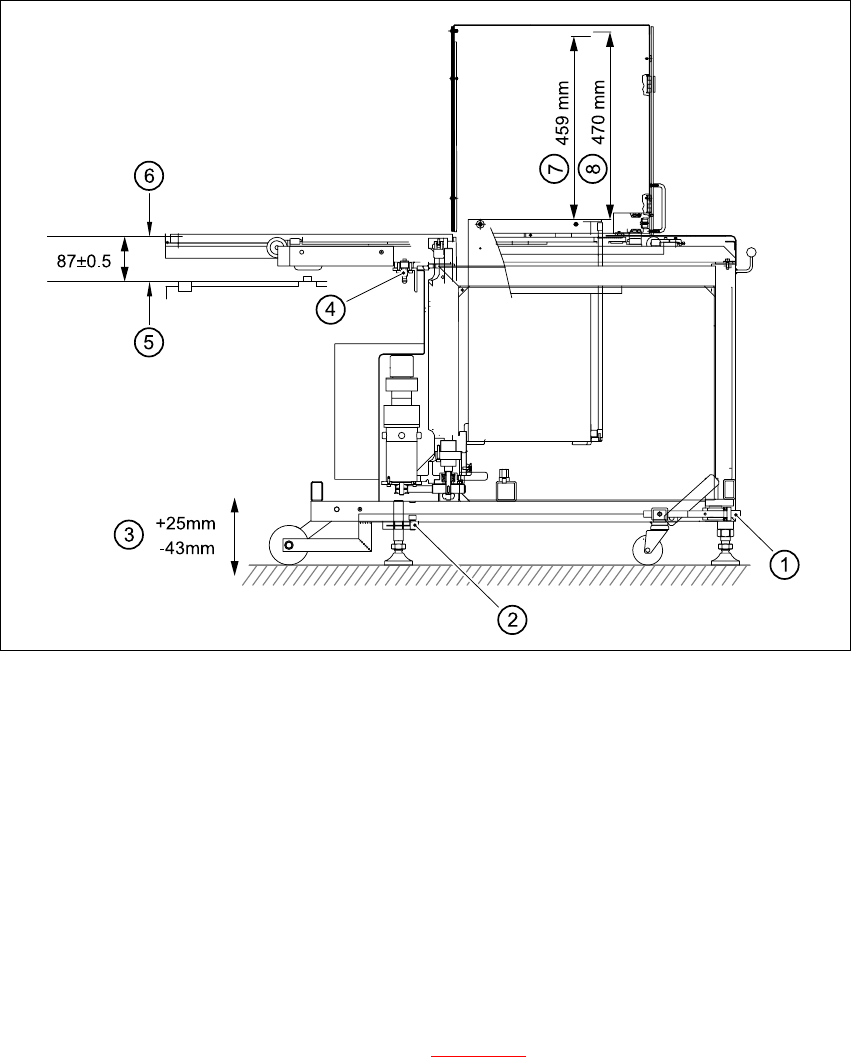
Fig. 6.6 - 6 Setting up the WPC
6
(1) Using UP/DOWN Allen key
(2) Clamping screw
(3) Stroke
(4) Docking pin
(5) Top edge of component feeder table magnetic rail
(6) Bottom edge of magazine carrier
(7) Nominal travel (459 mm)
(8) Refill position (470mm)
6
Æ Loosen the clamping screws on the feet (see Fig. 6.6 - 6) and use a 10 mm ball-tip Allen key
to turn the WPC down until docking pin engages. At the same time, align the WPC using the
machine's integral spirit level.
Æ Tighten the clamping screws and check the machine spirit level again.
Æ Place the top part of the camera on the component vision module once more.

User Manual SIPLACE CF 6 Component handling
Software version SR.101.xx 06/2003 US Edition 6.6 Waffle-pack changer
171
6.6.8 Technical data
6
6
Waffle-pack changer
Length Approx. 1475 mm
Width Approx. 620 mm
Height Approx. 1355 mm
Weight Approx. 240 kg
Vertical stroke 470mm
Horizontal stroke 730mm
Spacing 17mm
Storage capacity 28 magazine carriers for holding waffle-pack
trays
Magazine carriers 260 mm x 360 mm
Max. weight of the storage unit 50 kg
Floor loading < 25N/cm²
Max. magazine size 240 mm x 340 mm
Magazine height 15 mm, including component
Max. number of component types 200 per waffle-pack changer
Changeover time (magazine/magazine) ≤ 3 sec.

6 Component handling User Manual SIPLACE CF
6.7 Support for waffle-pack trays (manual tray) Software version SR.101.xx 06/2003 US Edition
172
6.7 Support for waffle-pack trays (manual tray)
PLEASE NOTE 6
The support for the waffle-pack magazine must only be placed on the right-hand component trol-
ley of the SIPLACE CF. The waffle-pack magazine support can only be positioned so that the
right edge fills no more than track 73. 6
6.7.1 General
The support for waffle-pack trays allows components to be picked up from individual waffle-pack
trays. The waffle-pack trays are changed manually.
The support for waffle-pack trays is placed on the component feeder table, just like a conveyor.
There are two different versions of the support, the only difference being the width.
Support for large waffle-pack tray
(260mmx360mm, fills 9 locations) part no. 00116430-01
Support for small waffle-pack tray
(136mmx360mm, fills 5 locations) part no. 00116432-01
6.7.2 Installation
Æ Insert the front side of the support for waffle-pack trays into the associated centering pin (B in
Fig. 6.7 - 1
).
Æ Then position the rear side of the support for the waffle-pack tray onto the centering ball on
the component feeder table (A in Fig. 6.7 - 1
).
Æ Check that the manual tray support is firmly seated on the component table.
Æ Position one side of the waffle-pack tray carrier in the mounting (C in Fig. 6.7 - 1). Then press
the other side into the mounting (D in Fig. 6.7 - 1
).
Æ Slide the waffle-pack tray up against the stop (E in Fig. 6.7 - 1).
Æ Secure the waffle-pack tray carrier by pressing the thrust pad (F in Fig. 6.7 - 1) downwards.
Æ To remove the waffle-pack tray carrier, press the thrust pad once more.
PLEASE NOTE 6
Using the support for small waffle-pack trays (136mm) a waffle-pack tray (JEDEC or CENELEC
waffle-pack tray) can be fitted directly to the support, in other words, without a waffle-pack tray
carrier being used. The thrust pad will require changing. 6