3OM-1208-011_w.pdf - 第121页
3-34 AIVEDT -ID 1.4 Placement Feeder Location Data (C01) Feeder Bases #1, #2, #3, #4, and Work Area It can be determined which components must be used and which feeder base (Fdr No.) must be loaded with the selected comp…

3-33
AIVEDT-ID
1.3 Placement Head/Nozzle Data
(B01_01)
Head 1, 2, 3, and 4
Nozzle 1 through 12, ID Names
This data is used to allocate the nozzles to the specified positions (Nozzle
Allocation Nos.) on the heads.
0606-009
1.3 Placement Head/Nozzle Data
3-34
AIVEDT-ID
1.4 Placement Feeder Location Data
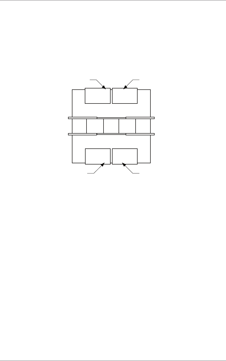
(C01) Feeder Bases #1, #2, #3, #4, and Work Area
It can be determined which components must be used and which feeder
base (Fdr No.) must be loaded with the selected components.
The tape feeders can be installed on the feeder bases.
Front Side of Machine
Rear Side of Machine
Feeder Base #1
Feeder Base #2
Feeder Base #3
Feeder Base #4
Fig. 3C26 Positional Relation between Feeder Bases
Work Area
The work area is the place where the data is stored temporarily.
This area is something like a virtual feeder base in which the data can
be stored temporarily and can be used to temporarily keep the data
overfl
owing after data conversion, pattern program creation, etc.
0606-009
1.4 Placement Feeder Location Data
3-35
AIVEDT-ID
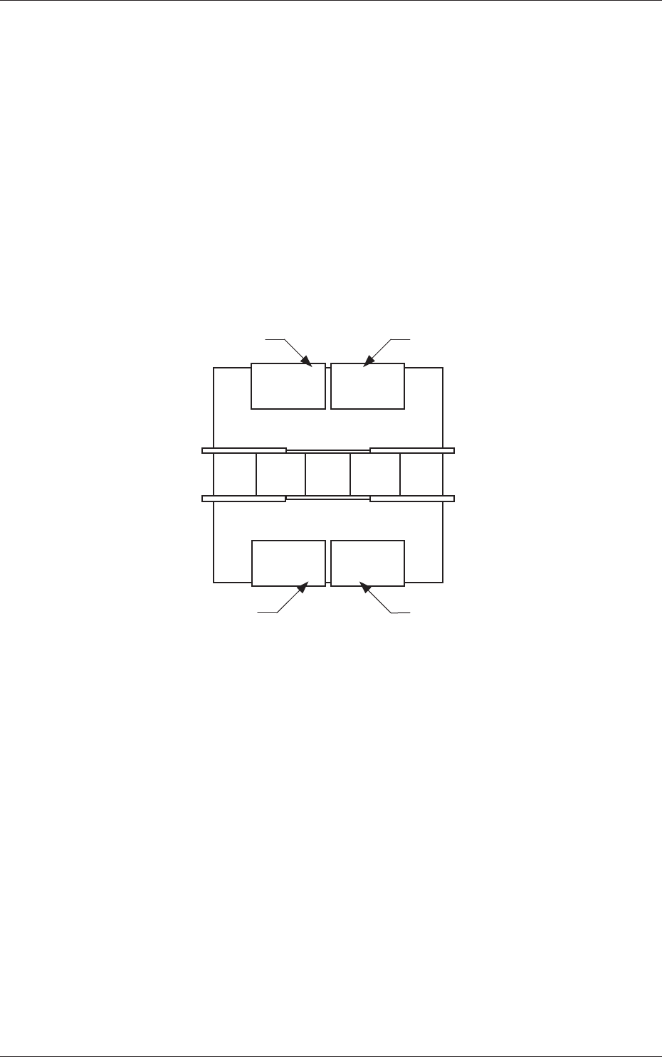
(C01_01)
Fdr No.
Shown are the feeder Nos. in the placement feeder location data.
The numbers in ( ) indicate the feeder Nos. that will actually be loaded
with components.
Feeder Base #1 :
101 to 150
Feeder Base #2 :
201 to 250
Feeder Base #3
:
301 to 350
Feeder Base #4 :
401 to 450
Work Area :
001 to 099
101 to 150 301 to 350
201 to 250 401 to 450
Front Side of Machine
Rear Side of Machine
Feeder Base #1
Feeder Base #2
Feeder Base #3
Feeder Base #4
Fig. 3C27
(C01_02)
Component ID
Set component IDs in the text boxes.
0606-009
1.4 Placement Feeder Location Data