3OM-1208-011_w.pdf - 第270页
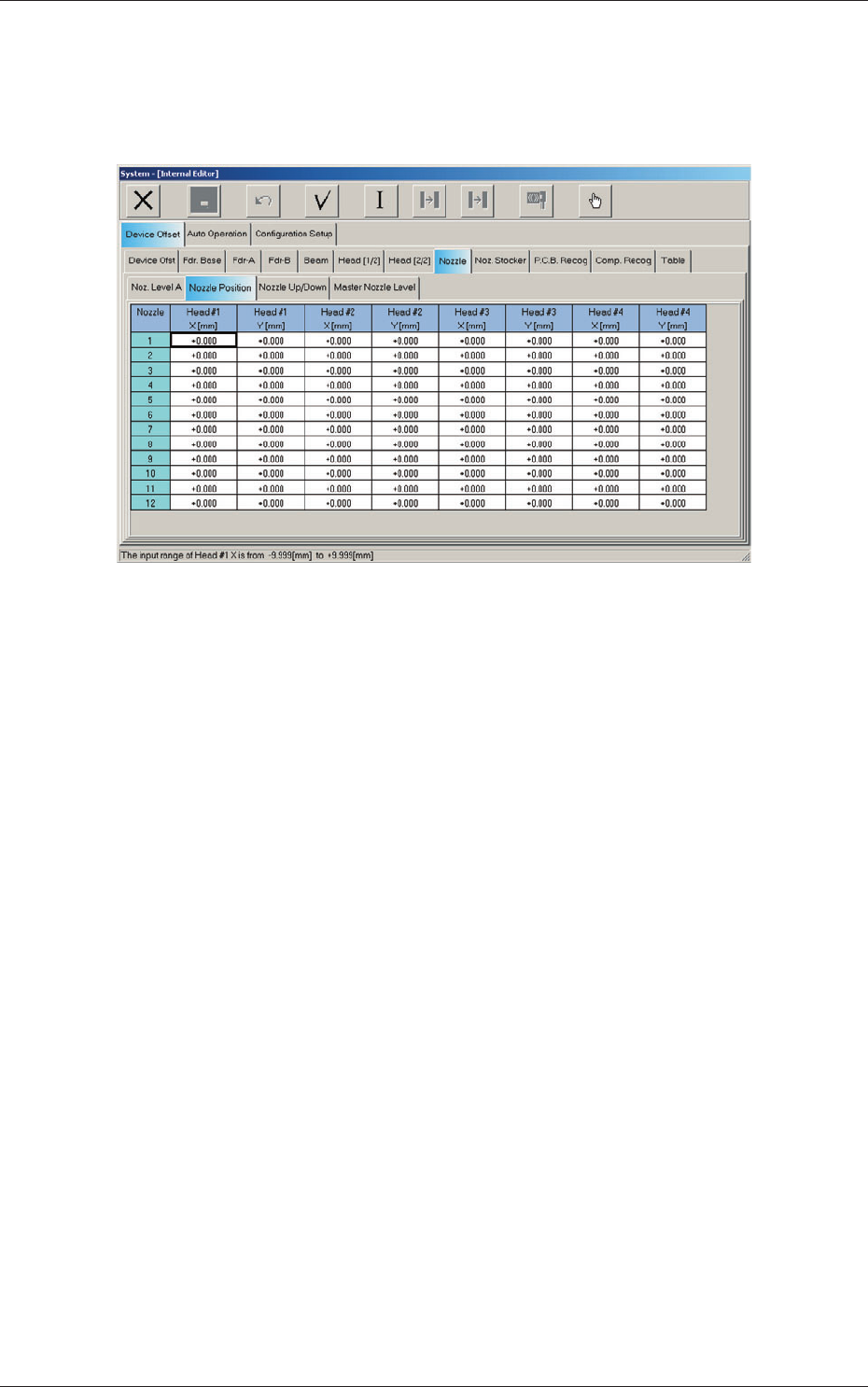
6-37 AIVEDT -ID Nozzles 1 through 12 Head #1, Head #2, Head #3, and Head #4 X (Horizontal), Y (V ertical) [mm] The set parameters are used to adjust the deviations from the design value between the head rotational center…
6-36
AIVEDT-ID
2.1.17 Nozzle Position Offset
When the "Nozzle" tab is pressed in the "Device Offset" tab sheet and the
"Nozzle Position" tab is selected, the following tab sheet appears.
Fig. 3F34 "Nozzle Position" Tab Sheet
2.1 Device Offset Data
0606-009
6-37
AIVEDT-ID
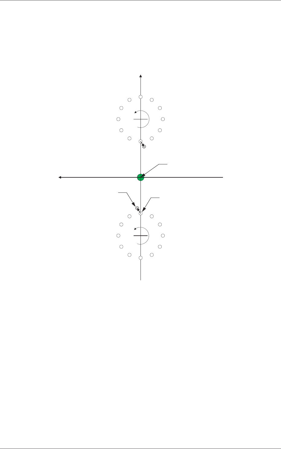
Nozzles 1 through 12
Head #1, Head #2, Head #3, and Head #4
X (Horizontal), Y (Vertical) [mm]
The set parameters are used to adjust the deviations from the design
value between the head rotational center and each nozzle end position.
Xm (+)
Ym (+)
Xm-Ym : Machine Reference
Coordinate System
DD (+)
DD (+)
1
3
4
5
6
7
8
9
10
11
12
1
2
3
4
5
6
7
8
9
10
11
12
Actual Nozzle Position
Pm. Machine Reference
Coordinate Origin
2
Design Value of Nozzle Position
Fig. 3F35
2.1 Device Offset Data
0606-009
6-38
AIVEDT-ID
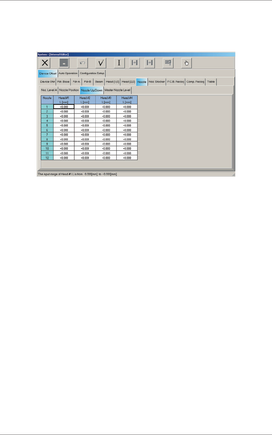
2.1.18 Nozzle Up/Down Offset
When the "Nozzle" tab is pressed in the "Device Offset" tab sheet and the
"Nozzle Up/Down" tab is selected, the following tab sheet appears.
Fig. 3F36 "Nozzle Up/Down" Tab Sheet
Nozzles 1 through 12
Head #1, Head #2, Head #3, and Head #4
L (Height) [mm]
The set parameters are the offsets based on the design value (gap)
between the upper surfaces of the nozzles and the nozzle U/D levers.
2.1 Device Offset Data
0606-009