3OM-1208-011_w.pdf - 第160页
3-73 AIVEDT -ID 0606-009 (5) P-data (U01) • Unit Control Create the data in the same way as described in "3.1 Single Pattern (Global Recognition Enabled)". • Unit PCB Fiducial T able 3C15 Unit PCB Fiducial Reco…
3-72
AIVEDT-ID
(2) Creation of Operation Data
•
PCB Data
Create the data in the same way as described in "3.1 Single Pattern (Global
Recognition Enabled)".
•
PEC Recognition Data
Table 3C13
PEC recognition function Enable
Correction algorithm Standard
PEC recognition
Mode
Global Zone 1 Disable
Zone 2 Disable
Zone 3 Disable
Zone 4 Disable
Zone 5 Disable
Image Enable
Iocal Disable
Beam Stage 1 Automatic (1 or 2)
Stage 2 Automatic (1 or 2)
Sequence Stage 1 After Pick Up
Stage 2 After Pick Up
•
PEC Recognition Mark Data
Table 3C14
Mark
No.
Mark
Size
D1 [mm]
1 Round 1.00 0.00 0.00
000.00 05.0 Bright High Standard Standard
(Normal)
Mark
Type
Mark
Size
D2 [mm]
Mark
Size
D3 [mm]
Angle
[deg]
Window
Size
[mm]
Mark
Image
Mark
Level
Lighting
Level
Coax
Lighting
Level
Ring
•
Setup Data
Create this data when the automatic setup function is used.
(3) Creation of Placement Head/Nozzle Data
Create the data in the same way as described in "3.1 Single Pattern (Global
Recognition Enabled)".
(4)
Creation of Placement Feeder Location Data
Create the data in the same way as described in "3.1 Single Pattern (Global
Recognition Enabled)".
0606-009
3.2 Repetitive Patterns (Image Recognition Enabled)
3-73
AIVEDT-ID
0606-009
(5) P-data (U01)
•
Unit Control
Create the data in the same way as described in "3.1 Single Pattern (Global
Recognition Enabled)".
•
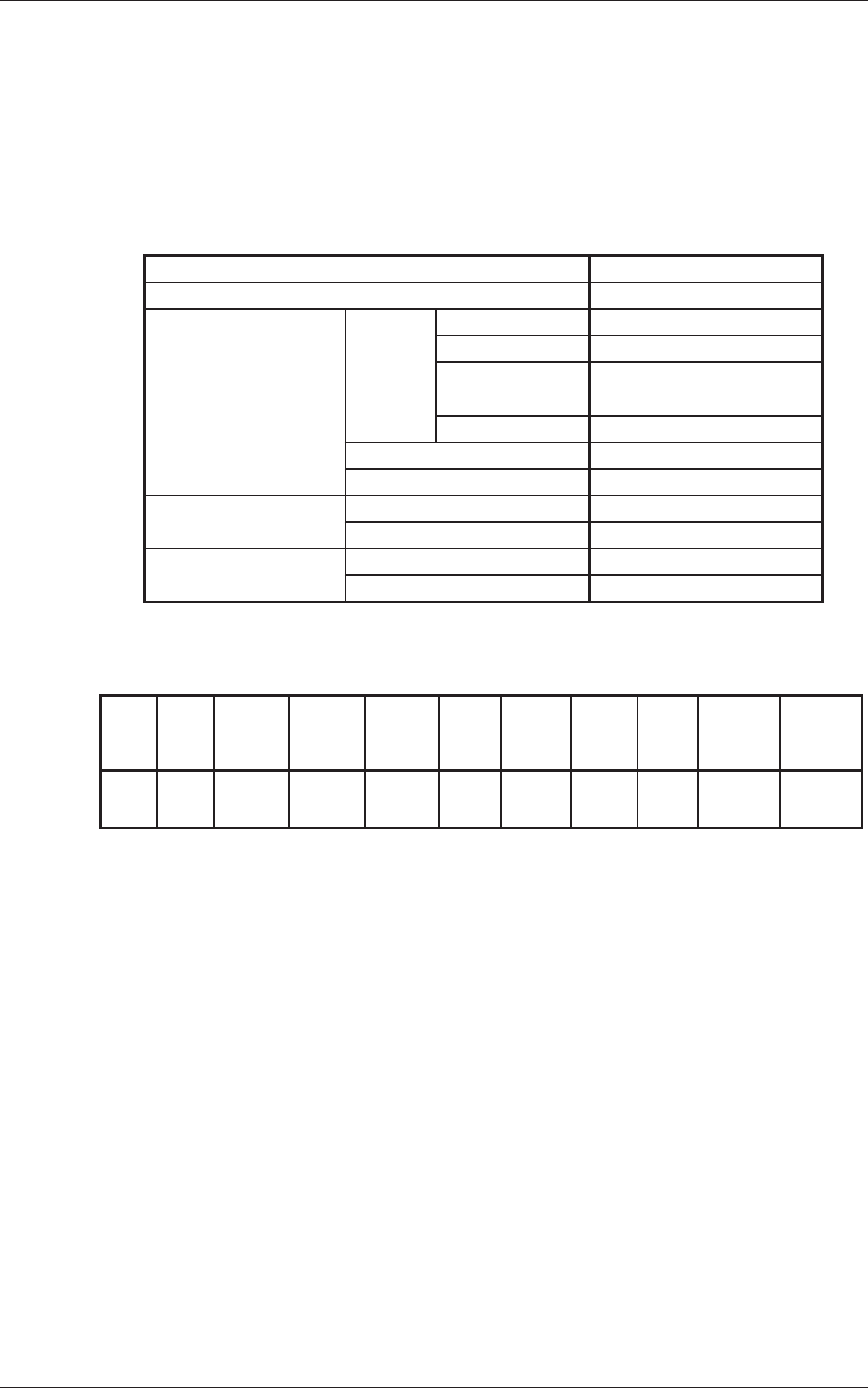
Unit PCB Fiducial
Table 3C15
Unit PCB
Fiducial
Recog Coord
X1 [mm]
Recog Coord
Y1 [mm]
Recog Coord
X2 [mm]
Recog Coord
Y2 [mm]
Fiducial Mark
FM1
Fiducial Mark
FM2
Enable FX
1
FY
1
FX
2
FY
2
1 1
•
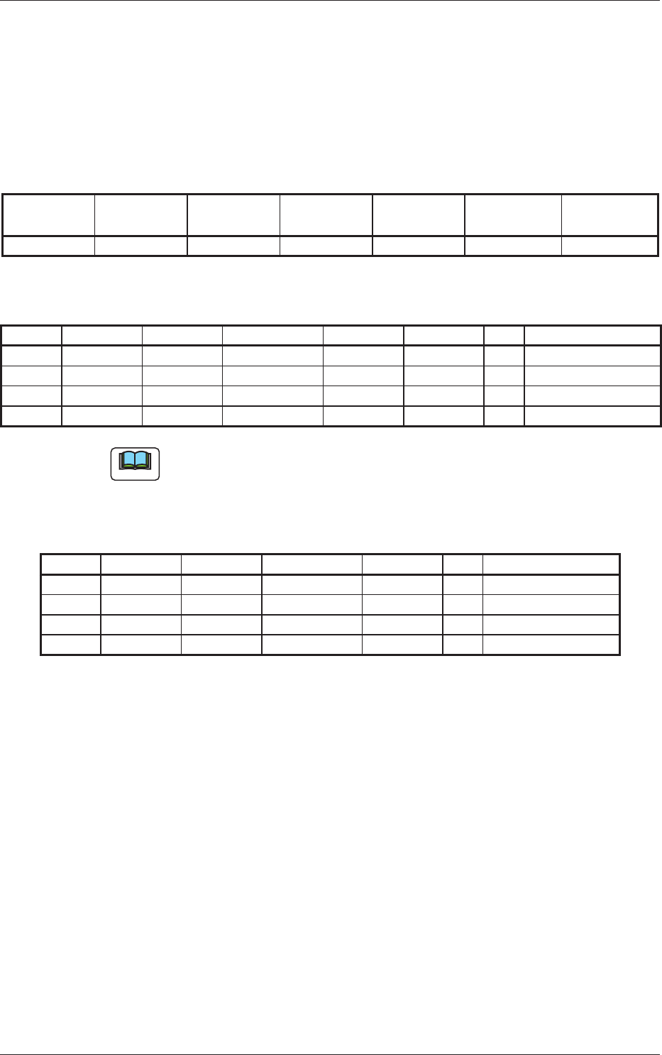
P-data
Table 3C16
P-No. X [mm] Y [mm] Z = theta [deg] H [mm] Fdr No. C Comment
1 X
1
Y
1
+000.00 +0.000 101 -
2 X
2
Y
2
+090.00 +0.000 103 -
3 X
3
Y
3
+180.00 +0.000 105 -
4 +000.000 +000.000 +000.00 +0.000 000 P
Note
Set "P" or "Q" in the "C" text box of the last step. "C" represents "Control
Command".
(6) O-data (U01)
Table 3C17
O-No. X [mm] Y [mm] Z = theta [deg] H C Comment
1 0X
1
0Y
1
+000.00 +0.000 -
2 0X
2
0Y
2
+000.00 +0.000 -
3 0X
3
0Y
3
+000.00 +0.000 -
4 +000.000 +000.000 +000.00 +0.000 P
3.2 Repetitive Patterns (Image Recognition Enabled)
3-74
AIVEDT-ID
3.3 Multi-Model Repetitive Patterns
(1) Information on Pattern Program Creation
•
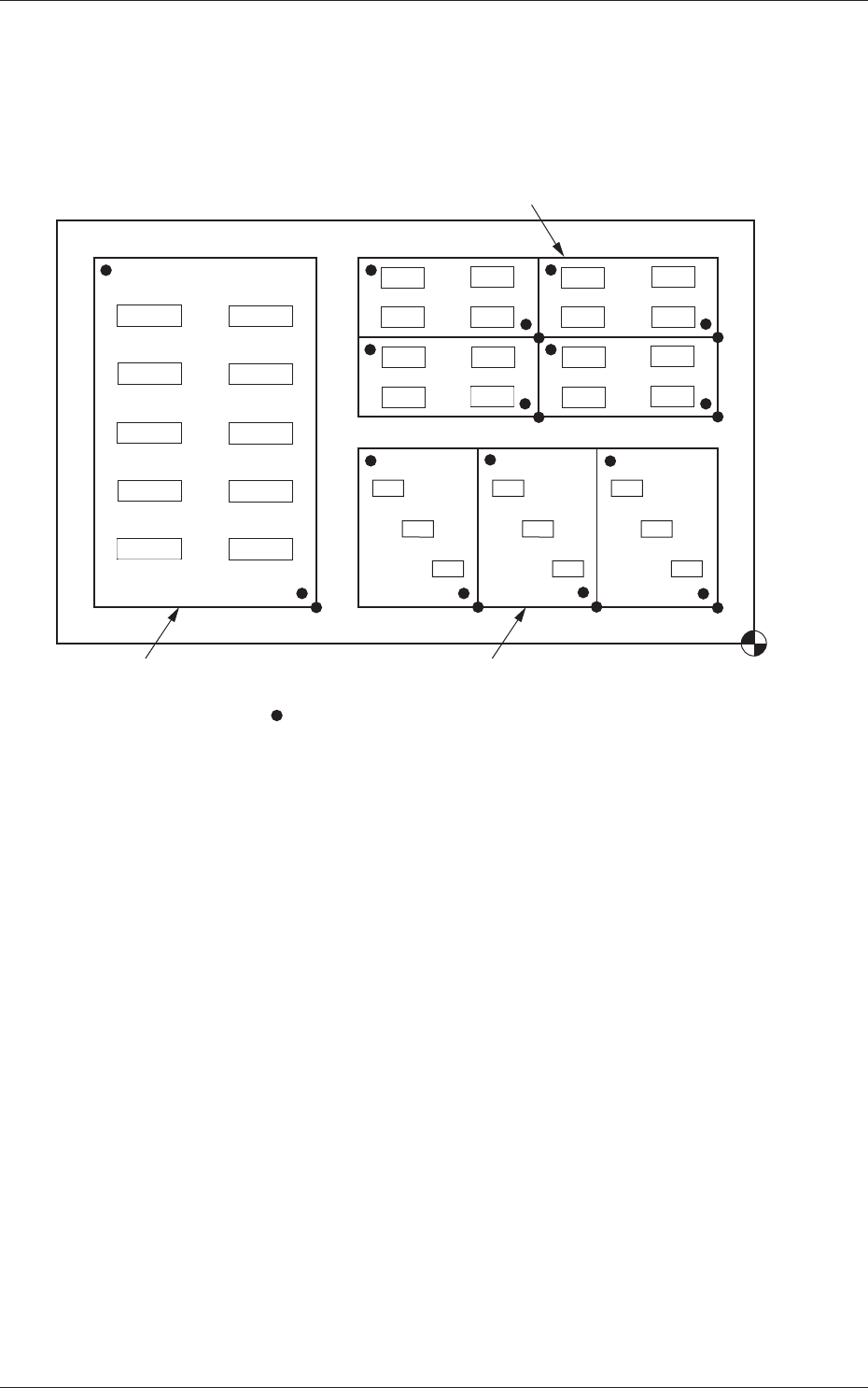
Example of Patterns
Placement
Coordinate
Reference
Pattern C
Pattern A
Pattern B
Pattern Origin (OX
3, OY3)
( signs are pattern origins.)
Fig. 3C56
The figure above shows that the mother board has eight unit PCBs (7 unit
PCBs for Patterns A and B and 1 unit PCB for Pattern C). Components are
placed repeatedly in regular order on each unit PCB for Patterns A and B,
forming repetitive patterns. In the case of Pattern C, components are placed
without forming any repetitive pattern.
0606-009
3.3 Multi-Model Repetitive Patterns