3OM-1208-011_w.pdf - 第126页
3-39 AIVEDT -ID 1.5.2 (D02) Placement Data (P-data) (D02_01) Unit Control Select one of the following options to determine whether the selected placement data (U01, U02, ..... Un) should be used. In normal cases, select …
3-38
AIVEDT-ID
0606-009
1.5 Placement Data
1.5.1 (D01) Placement Data Un
(D01_01)
Selection of Placement Data Unit
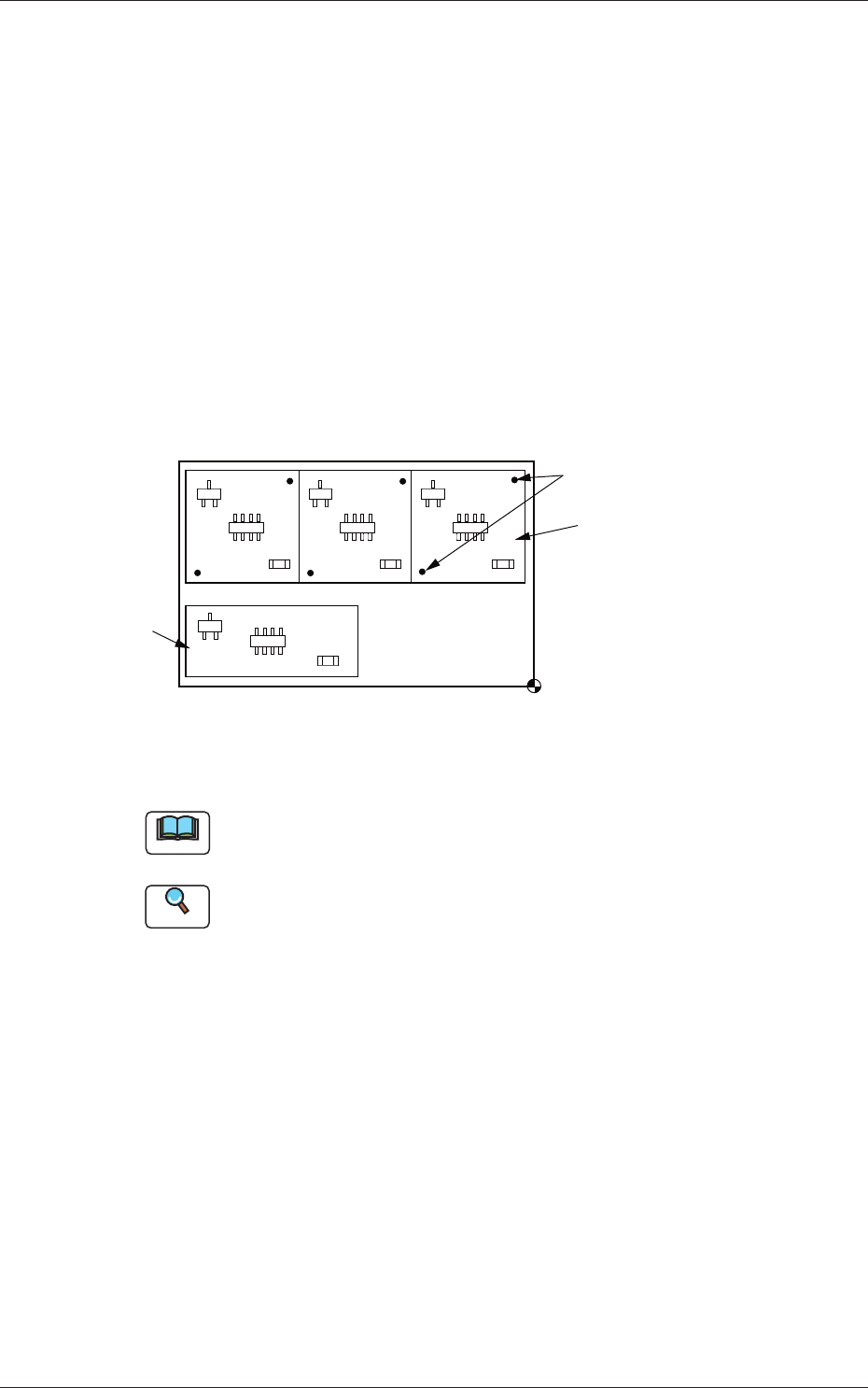
Select one of the following tabs (placement data groups) in one pattern
program.
U01 : First Placement Data Group
U02 : Second Placement Data Group
↓
Un
:
Up to 99 placement data groups can be specified.
U02
U01
Placement Coordinate
Reference
Fiducial Marks
Fig. 3C28 Example of Placement Data
Note
(a) Use "U01" in normal cases.
(b) The operation and feeder location data are used commonly.
Reference
Refer to "3. Example of Pattern Program Creation" for details.
1.5 Placement Data

3-39
AIVEDT-ID
1.5.2 (D02) Placement Data (P-data)
(D02_01)
Unit Control
Select one of the following options to determine whether the selected
placement data (U01, U02, ..... Un) should be used.
In normal cases, select "Placement".
Placement :
The placement data of the selected unit (group)
becomes valid.
Bypass :
The placement data of the selected unit (group)
becomes invalid.
(D02_02)
Placement Offset
Offset X [mm] and Offset Y
[mm]
Set the offset values for all placement coordinate X and Y in the
placement data (P-data) and the image and local PEC recognition
coordinates.
Note
(a) Use "+00.00" (zero) in normal cases.
(b) Note that these offsets are not reflected on "X [mm]" and "Y [mm]" in
"A02_04 Fiducial mark".
Offset Z [deg]
Set the offset value for all placement angles (Z=Theta) in the placement
data (P-data).
Note
Use "000.000" in normal cases.
Offset H [mm]
Set the offset value for all placement height "H" in the placement data
(P-data).
Note
In normal cases, set "+0.000" in this text box.
0606-009
1.5 Placement Data
3-40
AIVEDT-ID
(D02_03)
Unit PCB Fiducial
Select one of the following options to determine whether or not the unit
PCB BBR function should be used.
Disable :
The unit PCB BBR function is not used.
Enable :
The unit PCB BBR function (2-point recognition) is used.
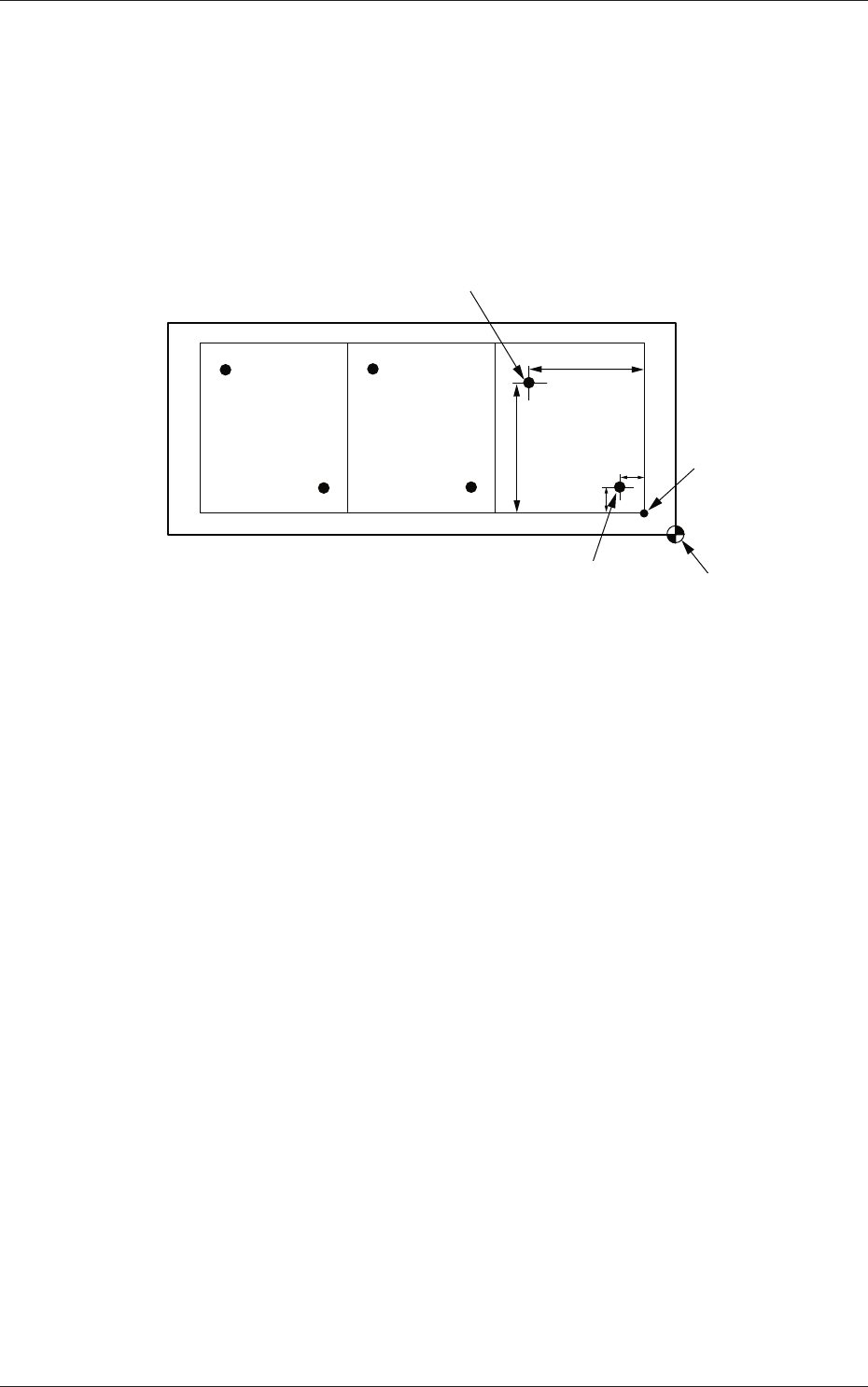
Y
1
X
2
Y
2
X
1
Second Fiducial Mark
Pattern Origin
First Fiducial Mark
Placement Coordinate
Reference
Fig. 3C29 Example of Unit PCB BBR Recognition
Recog Coord X1 [mm] and Recog Coord Y1 [mm]
Set the X1 and Y1 coordinates of the first fiducial mark based on the
pattern origin.
Recog Coord X2 [mm] and Recog Coord
Y2 [mm]
Set the X2 and Y2 coordinates of the second fiducial mark based on the
pattern origin.
Fiducial Mark FM1 and Fiducial Mark FM2
Set the mark Nos. of the first and second fiducial marks FM1 and FM2.
Select the mark Nos. (Mark Codes) specifi
ed in the PEC recognition
mark data of the operation data.
0606-009
1.5 Placement Data