3OM-1208-011_w.pdf - 第243页
6-10 AIVEDT -ID [5] Standard mark adjustment (A) The set parameters are used to adjust the deviations from the design position of the standard mark acquired during the teaching operation of the component recognition came…
6-9
AIVEDT-ID
0606-009
[3] PCB Transfer Positioning
Stage #1 and Stage #2
L->R1 (Back), R->L1 (Back),
L->R2 (Front), and R->L2 (Front) [mm]
Each parameters are used to correct the positional deviations in PCB
transfer positioning in comparison with "Support pin up/down".
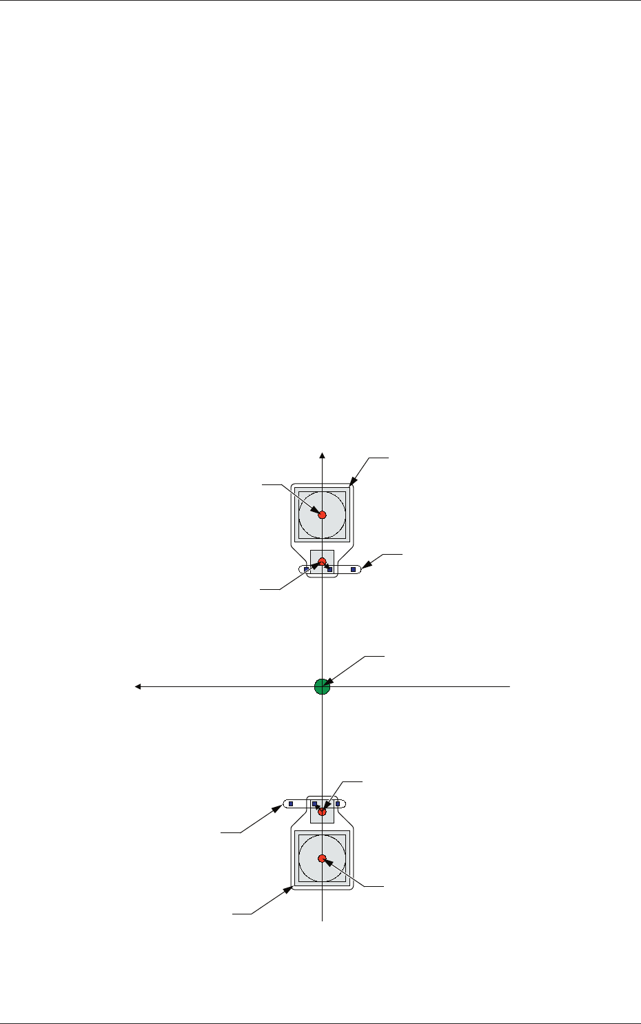
[4] Standard Mark
Head #1, Head #2, Head #3, and Head #4
Mark(L), Mark(M), Mark(R)
X(Horizontal) and Y(Vertical) [mm]
"Mark (M)" represents the standard mark position captured by the PEC
recognition camera when the rotational center of the head is moved to
the area above the component recognition camera.
"Mark (R)" and "Mark (L)" are the standard mark positions captured by
the PEC recognition camera when the pertinent nozzle is moved to the
center of the component recognition camera with the head being rotated
90
°
or 270
°
.
Xm (+)
Ym (+)
Component Recognition Camera
Component Recognition
Camera
Head Rotational Center
Head Rotational Center
Standard Mark
Standard Mark
Center of PEC Recognition Camera
Center of PEC Recognition
Camera
Pm. Machine Reference
Coordinate Origin
Fig. 3F10
2.1 Device Offset Data

6-10
AIVEDT-ID
[5] Standard mark adjustment (A)
The set parameters are used to adjust the deviations from the design
position of the standard mark acquired during the teaching operation of
the component recognition camera offsets.
Note
These parameters are used as reference values for the head rotational
center offset teaching.
[6] Standard mark adjustment (B)
The set parameters are used to adjust the deviations from the design
position of the standard mark acquired during the teaching operation of
the head rotational center offsets.
Note
The differences between "Standard mark adjustment (A)" and "Standard
mark adjustment (B)" are regarded as correction values for the head
rotational center offsets.
[7] Cutter
Block #1, Block #2, Block #3, and Block #4
Enter the parameters required to adjust the deviations in the cutter
adjustment position.
[8] Teaching Plate
Head #1, Head #2, Head #3, and Head #4
X (Horizontal), Y (Vertical), and L (Height) [mm]
Enter the parameters required to adjust the deviations based on the
design position of the jig depot.
[9]
Linear-Measure Sampling Size
Head #1, Head #2, Head #3, and Head #4
Set the number of dirt detection scanning times to be conducted by the
linear measure sensor of each head.
[10] Component Storage Box
Block #1, Block #2, Block #3, and Block #4
X (Horizontal), Y (Vertical), and L (Height) [mm]
The set parameters are used to correct the deviations from the design
position of the component storage box.
0606-009
2.1 Device Offset Data
6-11
AIVEDT-ID
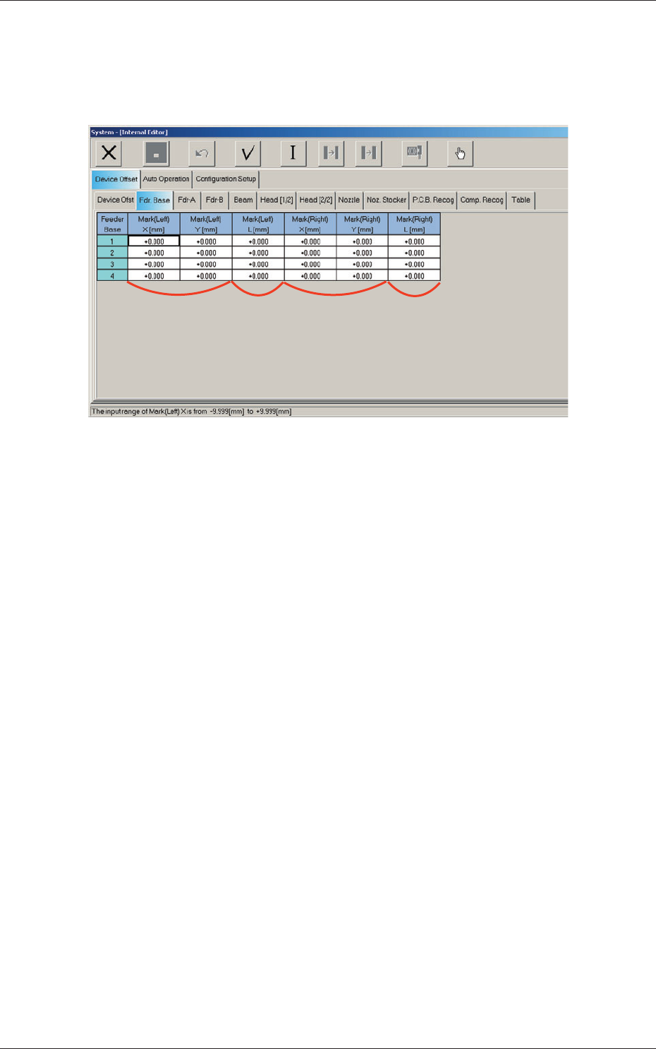
2.1.2 Feeder Base Offset
When the "Fdr. Base" tab is pressed in the "Device Offset" tab sheet, the
following tab sheet appears.
[1] [2] [3] [4]
Fig. 3F11 "Feeder Base" Tab Sheet
[1] Mark (Left)
X (Horizontal), Y (Vertical) [mm]
The set offset parameters are used to adjust the positional deviations
based on the design dimensions of Feeder Bases #1, #2, #3, and #4 (Rear
Side: #1 and #3, Front Side: #2 and #4). The values based on the PL-
XY coordinate system must be entered in the text boxes.
As for "Mark (Left) X and Y", the positional deviations are calculated
with the feeder base offset measurement jig being set on the left end of
the feeder base through recognition with the PEC recognition camera.
[2]
Mark (Left)
L (Height) [mm]
The set offset parameters are used to adjust the positional deviations
(height direction) based on the design dimensions of Feeder Bases #1,
#2, #3, and #4 (Rear Side: #1 and #3, Front Side: #2 and #4).
When the feeder bases are installed lower than the design values, a plus
value must be entered in each text box.
0606-009
2.1 Device Offset Data