ASM_Guide To Adhesive Dot Dispensing_Stinger_en_0321_online.pdf - 第14页
2 STINGER, A GUIDE TO ADHESIVE DOT DISPENSING 2.2 INTRODUCTION 14 GUIDE TO ADHESIVE DOT DISPENSING STINGER 03/2021 2.2.5 Laser Surface Height Detector The laser is used to detect the point where the upper surface of the …
2 STINGER, A GUIDE TO ADHESIVE DOT DISPENSING
2.2 INTRODUCTION
GUIDE TO ADHESIVE DOT DISPENSING STINGER 03/2021 13
1
2
3
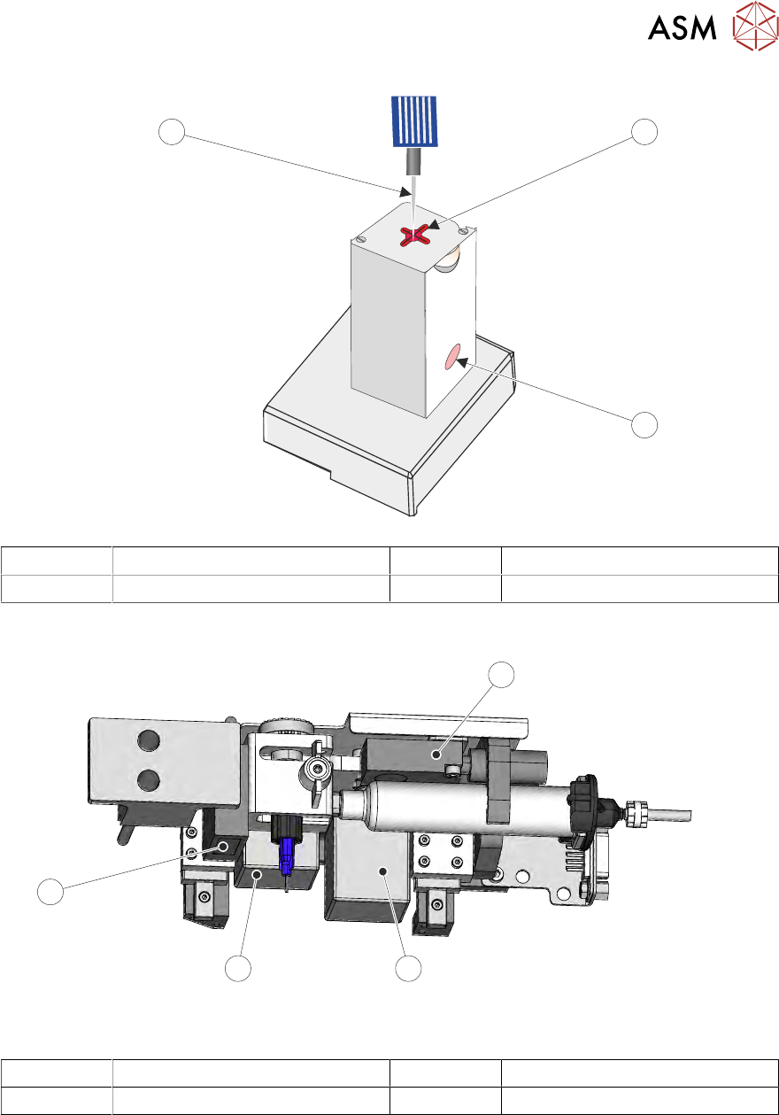
1 Wiper Target 3 Nozzle
2 Waste Container (pot)
2.2.3 Sensors and Motors
1
2
3
4
Stinger Unit Underneath Front View
1 Capacitive Level Sensor 3 Auger Drive Motor
2 Z-Axis Motor 4 Laser Surface Height Detector
2.2.4 Capacitive Level Sensor
The capacitive level sensor detects the change in capacitance of the surrounding near field area.
When a full cartridge is fitted, the capacitive field remains constant. As the adhesive in the syringe
is depleted, there is no change in capacitance until it reaches the point where the sensor is located.
The capacitive field changes and this change is indicated on the printer’s display interface. The
cartridge is changed and the level sensor is recalibrated to show a full condition.
2 STINGER, A GUIDE TO ADHESIVE DOT DISPENSING
2.2 INTRODUCTION
14 GUIDE TO ADHESIVE DOT DISPENSING STINGER 03/2021
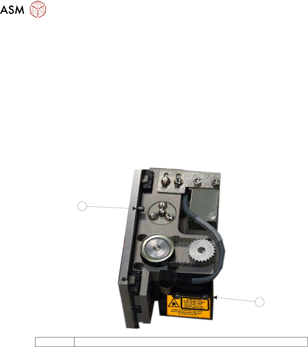
2.2.5 Laser Surface Height Detector
The laser is used to detect the point where the upper surface of the product is; this data is used to
calibrate the relative dispense height of the nozzle. The unit is automatically adjusted in software
and carries out its own calibration cycle as part of the set up routine. The LED’s on the front of the
unit can be ignored and the yellow button must not be adjusted.
2.2.6 Auger Motor
The auger motor drives the screw in the auger valve; the number of turns is set by a feed para-
meter in the software. The screw provides control over the amount of adhesive to be deposited and
‘works’ the adhesive to pre-condition it. This ensures that at the correct height, the nozzle deposits
a precise amount of adhesive to the product surface and flow is maintained throughout the deposit
cycle.
2.2.7 Z Axis Motor
The z axis motor drives the unit to this calibrated location. An end stop dowel provides a stall point
for the motor upper limit (see graphic). Refer to the Calibration section of this manual for details on
setting the calibrated heights for deposit and idle heights.
1
2
1 Yellow Button and LEDs 2 End Stop
2 STINGER, A GUIDE TO ADHESIVE DOT DISPENSING
2.2 INTRODUCTION
GUIDE TO ADHESIVE DOT DISPENSING STINGER 03/2021 15
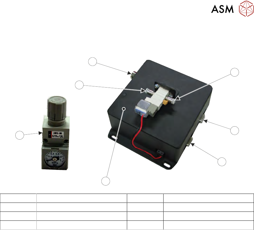
2.2.8 Control Interface
The control interface is situated on the frame at the rear of the printer. Next to this, is the pneumatic
air regulator, which supplies the air pressure to the syringe.
4
1
2
3
6
5
7
1 Air Input Connector 5 Pneumatic Regulator
2 Serial RS232 to PC 6 Air Output Connector
3 Stinger Power and Signal 7 Electrical Power In
4 Control Interface
The control interface is responsible for interfacing with the printing machine and locally controlling
Stinger’s functions: axis control, motor moves and air pulsing.