ASM_Guide To Adhesive Dot Dispensing_Stinger_en_0321_online.pdf - 第58页
2 STINGER, A GUIDE TO ADHESIVE DOT DISPENSING 2.8 APPENDIX 58 GUIDE TO ADHESIVE DOT DISPENSING STINGER 03/2021 2.8.2 Calibrating Stinger Heights (Manual) The height calibrations are a reference for all programmed deposit…
2 STINGER, A GUIDE TO ADHESIVE DOT DISPENSING
2.8 APPENDIX
GUIDE TO ADHESIVE DOT DISPENSING STINGER 03/2021 57
2.8 APPENDIX
2.8.1 Manual Offset Setup Procedure
This section describes the manual set up procedure that is to be employed if the Stinger unit:
●
Is being set up for the first time
●
Has been replaced
●
Is to be set up for a product changeover
Manual setup gives the user confidence that the unit is not going to drive directly into the stencil,
based on the software settings, when automatic height calibrations are performed. It also improves
the initial quality of the dispense process.
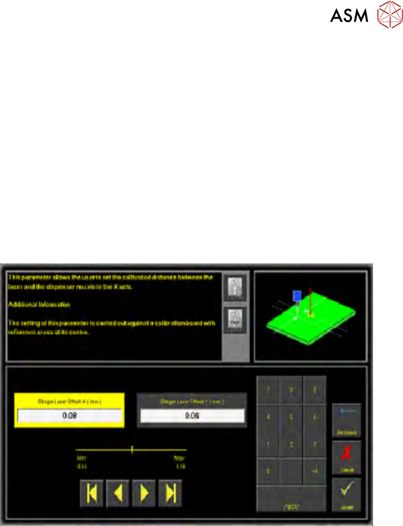
Stinger laser offsets allow the user to set the calibrated distance between the laser and the dis-
penser nozzle in the X and Y axes. Before this functionality is used, the camera reference point
must be calibrated. A calibration board, with a reference cross in its centre, is loaded into the
printer. The target location is measured and programmed from the centre of the wiper target cross,
to the centre of the camera reference dot on the front rail.
1. Select Stinger Laser Offset X (mm).
2. Measure, using a Steel Rule and an Engineers Square and modify the parameters in the X
axis.
3. Select Stinger Laser Offset Y (mm).
4. Measure, using a Steel Rule and an Engineers Square and modify the parameters in the Y
axis.
5. Select Accept.
2 STINGER, A GUIDE TO ADHESIVE DOT DISPENSING
2.8 APPENDIX
58 GUIDE TO ADHESIVE DOT DISPENSING STINGER 03/2021
2.8.2 Calibrating Stinger Heights (Manual)
The height calibrations are a reference for all programmed deposits. For non-automatic calibration
units, two heights are set: Contact Height and Idle Height. Idle height tracks the contact height
automatically; as determined by the idle height parameter.
The Z-Axis contact position, for any product, must be within (+/-1mm left screen above and
+/-1.5mm
right screen above) of the calibrated contact position. If the contact position cannot be
guaranteed to be within these limits, there is a likelihood that a variation in dot size may occur and
deposit quality degraded. An error page is displayed.
2 STINGER, A GUIDE TO ADHESIVE DOT DISPENSING
2.8 APPENDIX
GUIDE TO ADHESIVE DOT DISPENSING STINGER 03/2021 59
2.8.2.1 Setting Contact Height (Manual)
WARNING
BOARD CLAMPS. EXTREME CARE MUST BE EXERCISED WHEN WORKING IN
THE TOOLING AREA OF THE MACHINE TO AVOID INJURY. THE FOILS ON THE
FRONT AND REAR BOARD CLAMPS ARE VERY SHARP.
ADJUSTMENTS OR PERFORMANCE OF PROCEDURES OTHER THAN THOSE
SPECIFIED HEREIN MAY RESULT IN HAZARDOUS RADIATION EXPOSURE.
CAUTION
LASER/LED CONTROLS AND ADJUSTMENTS. USE OF CONTROLS OR
MANDATORY
TOXIC SUBSTANCES MAY BE PRESENT. SAFETY GLOVES MUST BE WORN.
MANDATORY
TOXIC SUBSTANCES MAY BE PRESENT. EYE PROTECTION MUST BE WORN.
Contact height sets the laser to nozzle tip height in relation to the upper surface of the product, it
becomes known to the system and a relative measure is made for all other programmed locations.
1. Ensure that the screen has been removed from the printer.
2. Select Setup Product.
3. Select Options.
4. Select Stinger Dispenser.
5. Select Load Board and load a product.
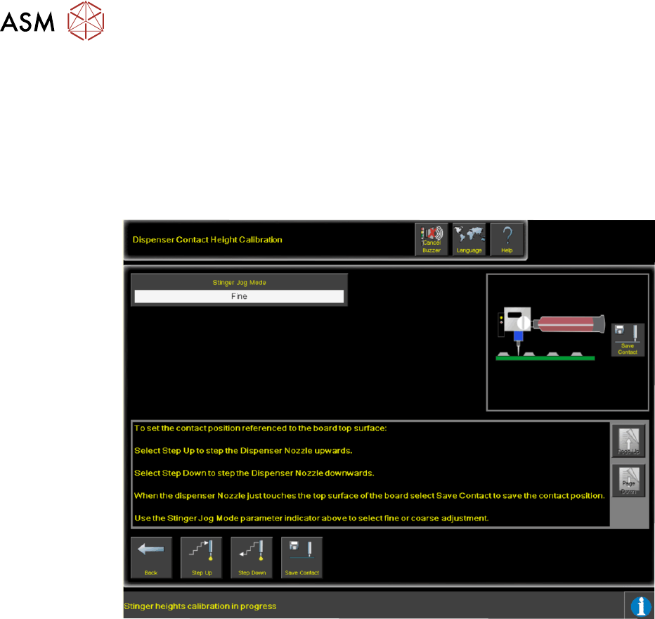
6. Select Manual Calibrate to open the dispenser contact height calibration page.
7. The camera axis moves the Stinger unit to the centre of board location by default, however,
this position can be set to any location using the Calibration Point X/Calibration Point Y
parameter pair. See information on siting the calibration point.
8. Select Stinger Jog Mode and initially set the mode to Coarse (1 step = 0.5mm).
9. Open the printhead cover.
10. Select Step Up or Step Down to move the nozzle into position just above the board (a min-
imum of six steps down.)
11. Place the 0.05mm feeler gauge on the board directly below the nozzle tip.
12. Select Stinger Jog Mode and set the mode to Fine (1 step = 0.05mm).
13. Continue jogging down until the feeler gauge has a small amount of resistance to being pulled
from under the nozzle.
Do not jog down beyond this point; any deflection of the board results in poor output
and must be avoided. The feeler gauge and the nozzle should not deflect the product down.
Any movement of the product away from the nozzle causes a discrepancy in the laser read-
ing.
14. Select Save Contact.
15. Select Back.