ASM_Guide To Adhesive Dot Dispensing_Stinger_en_0321_online.pdf - 第57页
2 STINGER, A GUIDE TO ADHESIVE DOT DISPENSING 2.8 APPENDIX GUIDE TO ADHESIVE DOT DISPENSING STINGER 03/2021 57 2.8 APPENDIX 2.8.1 Manual Offset Setup Procedure This section describes the manual set up procedure that is t…
2 STINGER, A GUIDE TO ADHESIVE DOT DISPENSING
2.7 ERROR RECOVERY
56 GUIDE TO ADHESIVE DOT DISPENSING STINGER 03/2021
2.7 ERROR RECOVERY
Symptom Possible Cause Solution
Product surface being pushed
down during dispense
Contact height incorrectly calib-
rated
Re-calibrate Contact Height.
Ensure that the product is not
deflected and that the cali-
bration board is representative
of the production boards
Inconsistent deposit Product warpage is present but
laser correction is not being
used
Switch on laser measurement
for deposit sites
Inconsistent deposit Product warpage is greater
than +\- 1mm
Use vacuum tooling or a
product that is within tolerance
Dispense motor is turning, but
no material is being dispensed
System needs purging, pos-
sible drying of adhesive
Purge the system, if the condi-
tion persists change the dis-
pense feed path assembly
Dispense motor not turning Dispense motor belt tension too
tight
Reduce belt tension
Dispense motor timed out Dispense motor stalled due to
adhesive drying out and form-
ing a blockage
Discard and replace the dis-
pense feed path assembly
No feed Adhesive dried in feed path Discard and replace the dis-
pense feed path assembly
Inconsistent delivery, particu-
larly during a purge
No air Ensure that the syringe is being
pressurised (pulsed) during dis-
pense and purge routines
Dispense site outside of board
area error
Site location incorrectly pro-
grammed
Continue, and ignore the warn-
ing. Skip the offending site or
Stop the print run, and re pro-
gramme the site location for the
correct location; or remove the
site altogether
Auto-Calibrate Fails Calibrate X and Y location
incorrectly set
Locate the calibration point so
that neither the laser nor the
nozzle are over board cut-outs
Auto-Calibrate Fails Vision height or other variable
has been changed
Perform a manual calibrate to
reset the laser range
2 STINGER, A GUIDE TO ADHESIVE DOT DISPENSING
2.8 APPENDIX
GUIDE TO ADHESIVE DOT DISPENSING STINGER 03/2021 57
2.8 APPENDIX
2.8.1 Manual Offset Setup Procedure
This section describes the manual set up procedure that is to be employed if the Stinger unit:
●
Is being set up for the first time
●
Has been replaced
●
Is to be set up for a product changeover
Manual setup gives the user confidence that the unit is not going to drive directly into the stencil,
based on the software settings, when automatic height calibrations are performed. It also improves
the initial quality of the dispense process.
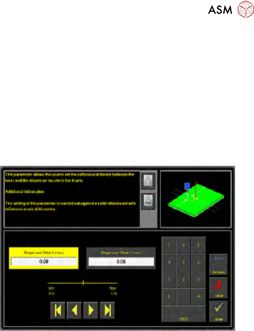
Stinger laser offsets allow the user to set the calibrated distance between the laser and the dis-
penser nozzle in the X and Y axes. Before this functionality is used, the camera reference point
must be calibrated. A calibration board, with a reference cross in its centre, is loaded into the
printer. The target location is measured and programmed from the centre of the wiper target cross,
to the centre of the camera reference dot on the front rail.
1. Select Stinger Laser Offset X (mm).
2. Measure, using a Steel Rule and an Engineers Square and modify the parameters in the X
axis.
3. Select Stinger Laser Offset Y (mm).
4. Measure, using a Steel Rule and an Engineers Square and modify the parameters in the Y
axis.
5. Select Accept.
2 STINGER, A GUIDE TO ADHESIVE DOT DISPENSING
2.8 APPENDIX
58 GUIDE TO ADHESIVE DOT DISPENSING STINGER 03/2021
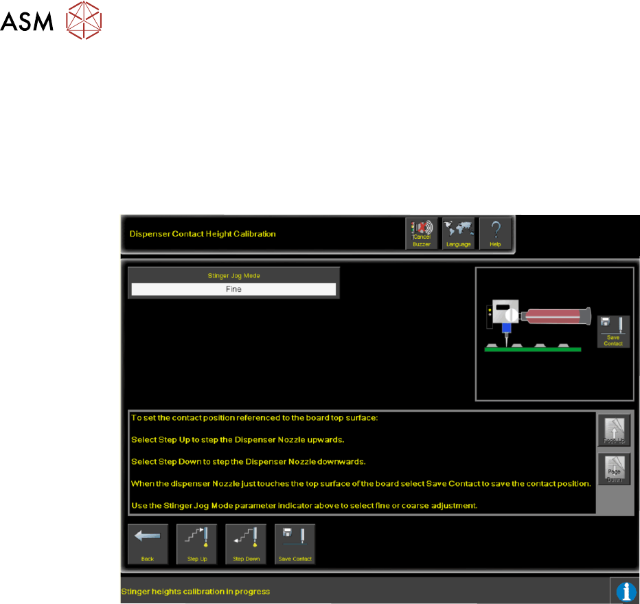
2.8.2 Calibrating Stinger Heights (Manual)
The height calibrations are a reference for all programmed deposits. For non-automatic calibration
units, two heights are set: Contact Height and Idle Height. Idle height tracks the contact height
automatically; as determined by the idle height parameter.
The Z-Axis contact position, for any product, must be within (+/-1mm left screen above and
+/-1.5mm
right screen above) of the calibrated contact position. If the contact position cannot be
guaranteed to be within these limits, there is a likelihood that a variation in dot size may occur and
deposit quality degraded. An error page is displayed.