ASM_Guide To Adhesive Dot Dispensing_Stinger_en_0321_online.pdf - 第61页
2 STINGER, A GUIDE TO ADHESIVE DOT DISPENSING 2.8 APPENDIX GUIDE TO ADHESIVE DOT DISPENSING STINGER 03/2021 61 3. Select Stinger Dispenser . 4. Select Setup Sites . 5. Select Create Site . 6. Set the dispense mode to Mea…
2 STINGER, A GUIDE TO ADHESIVE DOT DISPENSING
2.8 APPENDIX
60 GUIDE TO ADHESIVE DOT DISPENSING STINGER 03/2021
16. The camera axis moves the unit to the right hand edge of the board. This is the Range Posi-
tion where the unit performs a Range Check.
17. The nozzle moves down, either 1mm or 1.5mm dependent upon which Stinger option is fitted,
from contact height.
18. The nozzle moves up through contact height to 1mm or 1.5mm above contact height. This
completes the Range Check.
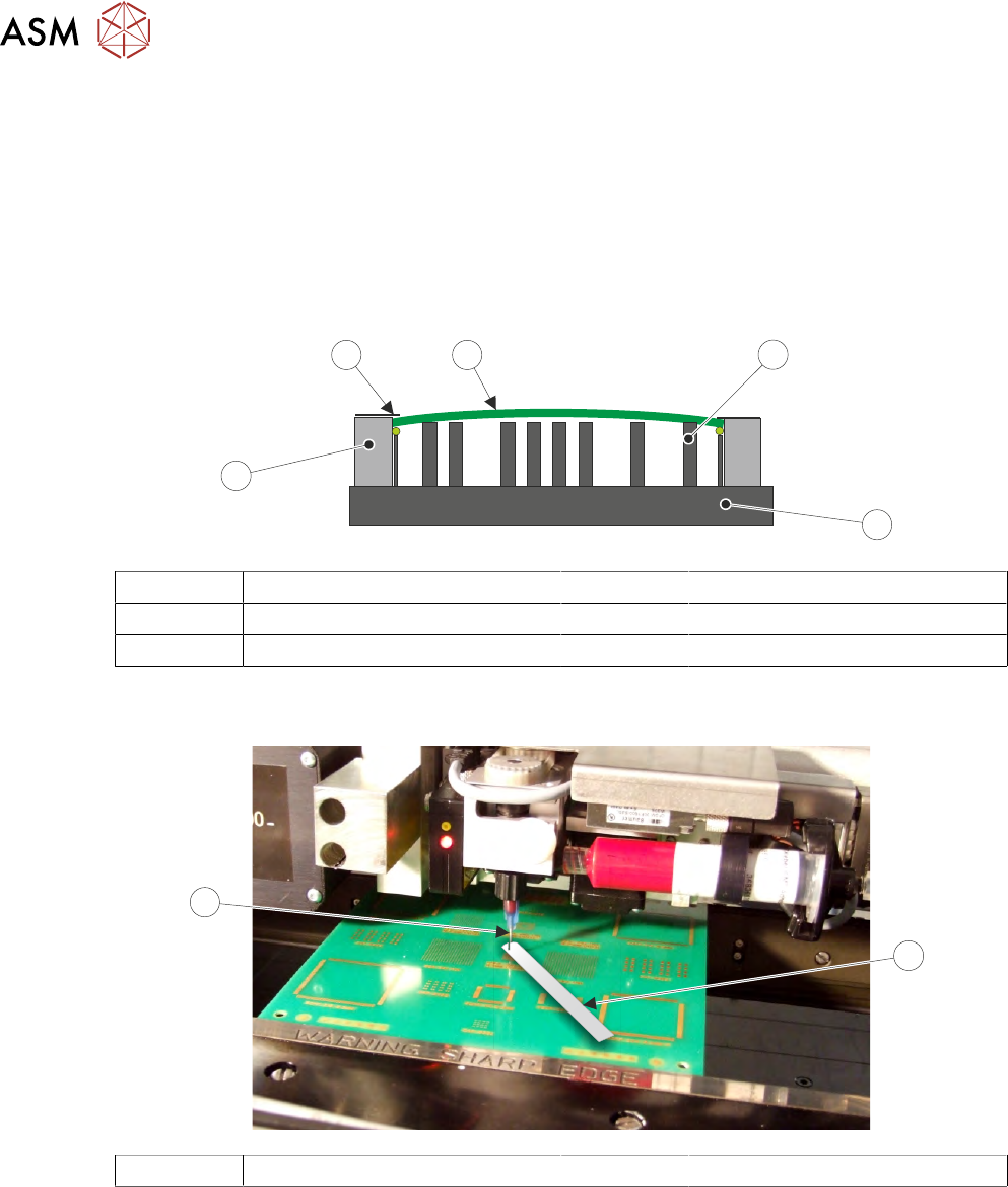
Board Clamps may cause boards to bow slightly in the centre.
This may cause the measurement to fall outside the 0.1mm minimum Z Axis contact position.
1
2
4
3
5
1 Tooling 4 Board Clamps
2 Rising Table 5 Board
3 Rails
The feeler gauge thickness is the equivalent of one step of the Z Axis stepper motor. It is essential
that when setting this contact point no board deflection occurs.
1
2
1 Feeler Gauge 2 Nozzle Tip
For non-automatic calibration options, the user must set the idle height next. For automatic cali-
bration options, the idle height parameter has been programmed in Setup Product\Options
\Stinger Dispenser and the unit can track this value above contact height. Stinger can track the
rises and falls on the product surface within the range check limits.
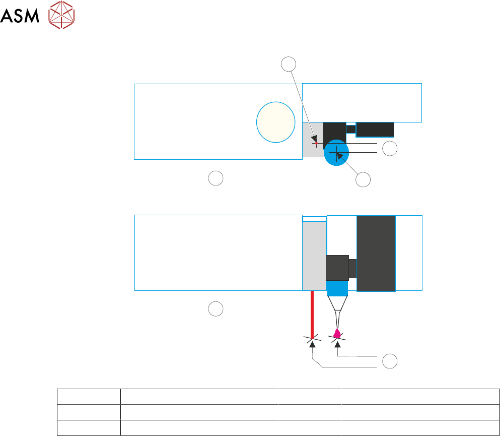
2.8.2.2 Stinger Laser Offsets X and Y
This parameter sets a factor to compensate for any offsets of the nozzle to laser, in the X and Y
planes, at the point where the laser actually measures. This can be any value between -5mm
and
5mm
. As with the calibrated offsets, a deposit point is marked on the calibration board. The offset
is set to zero and a deposit is made; the difference between the deposit centre and the laser centre
is the amount of compensation to be set.
1. Select Setup Product.
2. Select Options.

2 STINGER, A GUIDE TO ADHESIVE DOT DISPENSING
2.8 APPENDIX
GUIDE TO ADHESIVE DOT DISPENSING STINGER 03/2021 61
3. Select Stinger Dispenser.
4. Select Setup Sites.
5. Select Create Site.
6. Set the dispense mode to Measure Only (on a single site).
7. Select Confirm.
8. Select Back.
9. Select Load Screen.
10. Open the cover.
11. Cover the screen present sensor and select Continue. The screen clamps actuate.
12. Select Back.
13. Select Fiducials.
14. Select Global Settings.
15. Select Alignment Mode.
16. Select Non Vision.
17. Select Accept.
18. Select Back.
19. Select Back.
20. Select Options.
21. Select Stinger Dispenser.
22. Select Load Board. Choose the preferred load board method, auto or manual.
23. Select Dispense Sweep.
24. Select Back.
25. Select Open Cover Commands.
26. Open the printhead front cover.
27. Measure the Laser Offset X and Y between the dispensed dot and the laser beam position.
The object must have the laser beam shining on the dot centre. Edit the laser X and Y offsets
as required (see illustration at end of procedure).
28. Close the printhead front cover.
29. Select Save.
30. Select Setup Sites.
31. Select Adjust Site, set the dispense mode to its original state.
32. Select Fiducials.
33. Select Confirm.
34. Select Back.
35. Select Back.
36. Select Back.
2 STINGER, A GUIDE TO ADHESIVE DOT DISPENSING
2.8 APPENDIX
62 GUIDE TO ADHESIVE DOT DISPENSING STINGER 03/2021
1
2
A
3
B
4
A Top View 2 Y Offset
B Front View 3 Nozzle Centre
1 Laser Centre 4 X Offset