KD-2077_SPE_EN.pdf - 第12页
8 4.3 Recommended Glues • Henkel Jap an Ltd. Lo ctit e 3609 • Heraeus K.K. PD955M • SOMAR Corporatio n IR - 120H 4.4 T arget PWB 4.4.1 P W B tra nsportin g direc tion Flo w to the right (trans port from the l eft to the …
7
4.2.3 Resolution
Z axis: 5 μm
θ axis: 0.01º
4.2.4 Dispensing angle setting
0º to 359º (in units of 1º)
4.2.5 Applicable syringe
Recommended syringe: Made of Iwashita engineering, Inc. PS30S
Capacity: 30 cc
4.2.6 Applicable needles
Needle
name
Target component
width
Main applicable component
S
0.8 to 1.25
1608, SOT (mold part 1.6 x 0.8)
CS
Ditto
Ditto (for high-density dispensing)
M
1.25 to 2.5
2012, 3216, SOT (mold part 2.0 x 1.25), SOT23
CM
Ditto
Ditto (for high-density dispensing)
L 2.5 to 4.0
Aluminum electrolytic condenser, tantalum condenser,
trimmer, MELF, etc.
LL
7 to 10
Aluminum electrolytic condenser, SOP, QFP, etc.
XL
10 to
QFP, etc.
S-WST
0.8 to 1.25
1608, SOT (mold part 1.6 x 0.8)
* The S-WST needle is a 2-points stopper type.
4.2.7 Discharge needles
Needle
name
Part No Number of dots
Internal
diameter(mm)
Pitch between
needle holes(mm)
S
E3401802000
2
0.3
0.7
CS
E3402802000
2
0.4
0.7
M
E3406802000
2
0.4
1.0
CM
E3407802000
2
0.4
1.0
L
E3411802000
1
0.6
-
LL
E3416802000
2
0.9
2.0
XL
E3421802000
4
0.9
1.5
S-WST
40028869
2
0.3
0.7
* If any needle shape other than the above is required, consult with JUKI Business Department.
However, the dispensing shape, dispensing accuracy, dispensing tact, residual amount
notification, and air volume correction may not be assured.
4.2.8 Residual amount detecting function
This function measures and detects the exhaust time of the air volume section in the syringe.
When the residual glue volume reaches 4 cc, a warning is output or the machine is temporarily
stopped.
4.2.9 Air volume correcting function
When the residual amount of glue is small, the dispensing amount is decreased. For stable
dispensing, the residual amount in the syringe is measured and the inside of the syringe is
automatically pressurized to keep the dispensing amount at a certain level.
4.2.10 Temperature regulating function
3-head independent regulation
Set temperature range: 30ºC to 45ºC (in units of 1ºC)

8
4.3 Recommended Glues
• Henkel Japan Ltd. Loctite 3609
• Heraeus K.K. PD955M
• SOMAR Corporation IR-120H
4.4 Target PWB
4.4.1 PWB transporting direction
Flow to the right (transport from the left to the right as viewed from the front)
Flow to the left (transport from the right to the left as viewed from the front)
* The direction of flow is determined at delivery form the factory.
4.4.2 PWB dimensions
Minimum dimensions (L x W): 50 x 30 mm
50 x 50 mm when an auto PWB width alignment function is provided.
Maximum dimensions (L x W): 410 x 360 mm
Thickness: 0.4 to 4.0 mm (actual thickness)
Note: Regarding the transporting direction, W is at a right angle to L and W/L is 2 or less.
4.4.3 PWB mass
2,000 g or less
9
4.4.4 PWB parameter limits
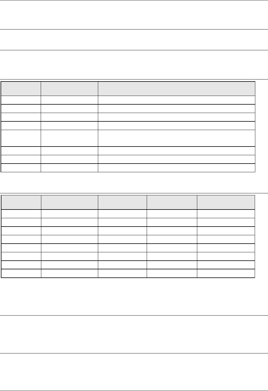
4.4.4.1 Not allowed dispensing area of the top surface
Figure 1 Top surface of PWB (shape reference specification)
Note 1: In the case where the auto PWB width aligning function (option) is provided, the
minimum length is 50 mm.
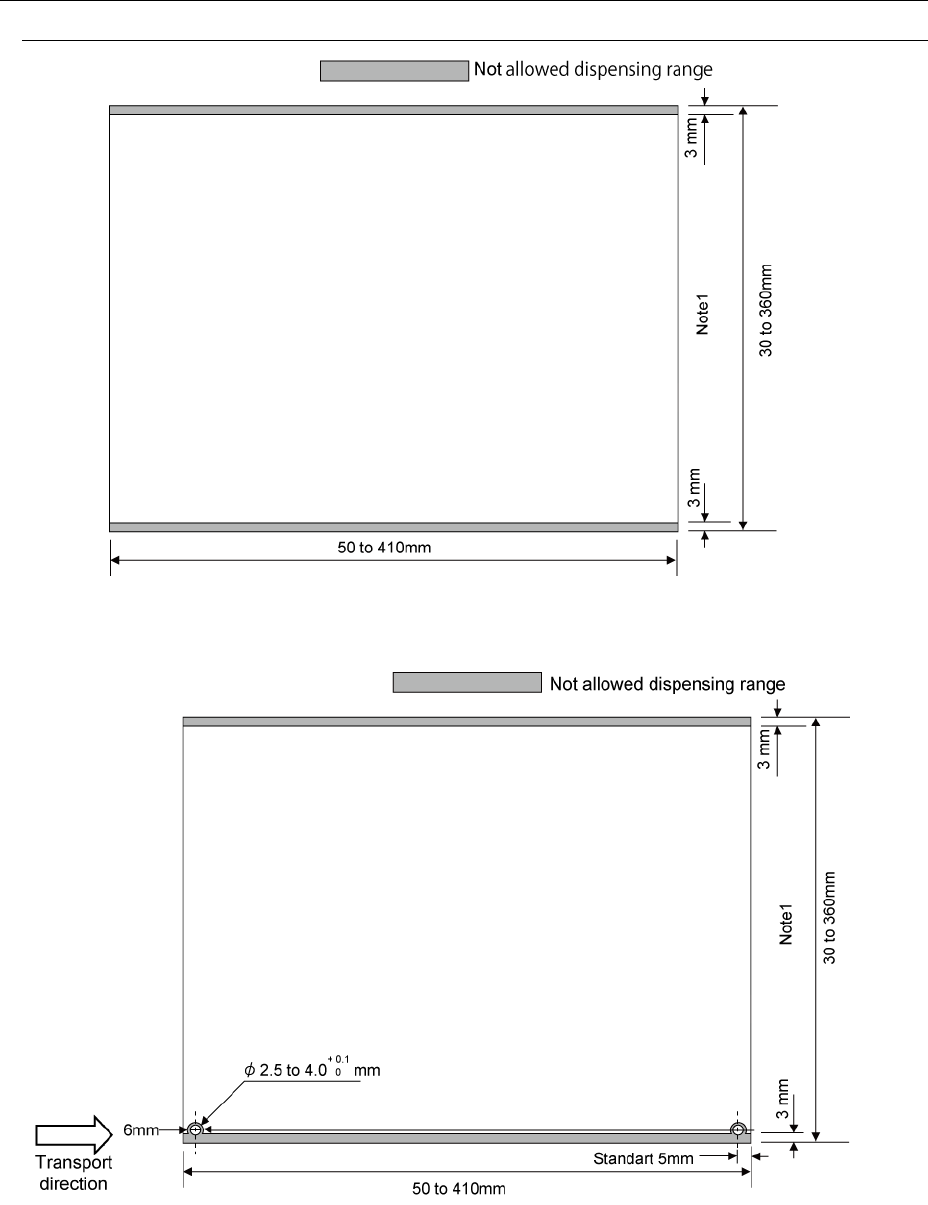
Figure 2 Top surface of PWB (pin reference (option) specification)
Note 1: In the case where the auto PWB width aligning function (option) is provided, the
minimum length is 50 mm.
Note : Dimensions at delivery from the factory. The reference pin position in the transporting
direction can be changed on the user side for all the PWB length.