KD-2077_SPE_EN.pdf - 第13页
9 4.4.4 P W B p arameter limit s 4.4.4.1 N ot allow ed dispensi ng area o f the top surface Figure 1 T op surfac e of PWB (shape reference specific ation) Note 1: In the case wh ere the auto PWB wid th alig ning function…

8
4.3 Recommended Glues
• Henkel Japan Ltd. Loctite 3609
• Heraeus K.K. PD955M
• SOMAR Corporation IR-120H
4.4 Target PWB
4.4.1 PWB transporting direction
Flow to the right (transport from the left to the right as viewed from the front)
Flow to the left (transport from the right to the left as viewed from the front)
* The direction of flow is determined at delivery form the factory.
4.4.2 PWB dimensions
Minimum dimensions (L x W): 50 x 30 mm
50 x 50 mm when an auto PWB width alignment function is provided.
Maximum dimensions (L x W): 410 x 360 mm
Thickness: 0.4 to 4.0 mm (actual thickness)
Note: Regarding the transporting direction, W is at a right angle to L and W/L is 2 or less.
4.4.3 PWB mass
2,000 g or less
9
4.4.4 PWB parameter limits
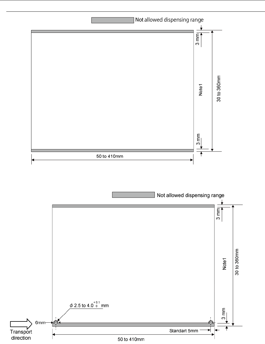
4.4.4.1 Not allowed dispensing area of the top surface
Figure 1 Top surface of PWB (shape reference specification)
Note 1: In the case where the auto PWB width aligning function (option) is provided, the
minimum length is 50 mm.
Figure 2 Top surface of PWB (pin reference (option) specification)
Note 1: In the case where the auto PWB width aligning function (option) is provided, the
minimum length is 50 mm.
Note : Dimensions at delivery from the factory. The reference pin position in the transporting
direction can be changed on the user side for all the PWB length.
10
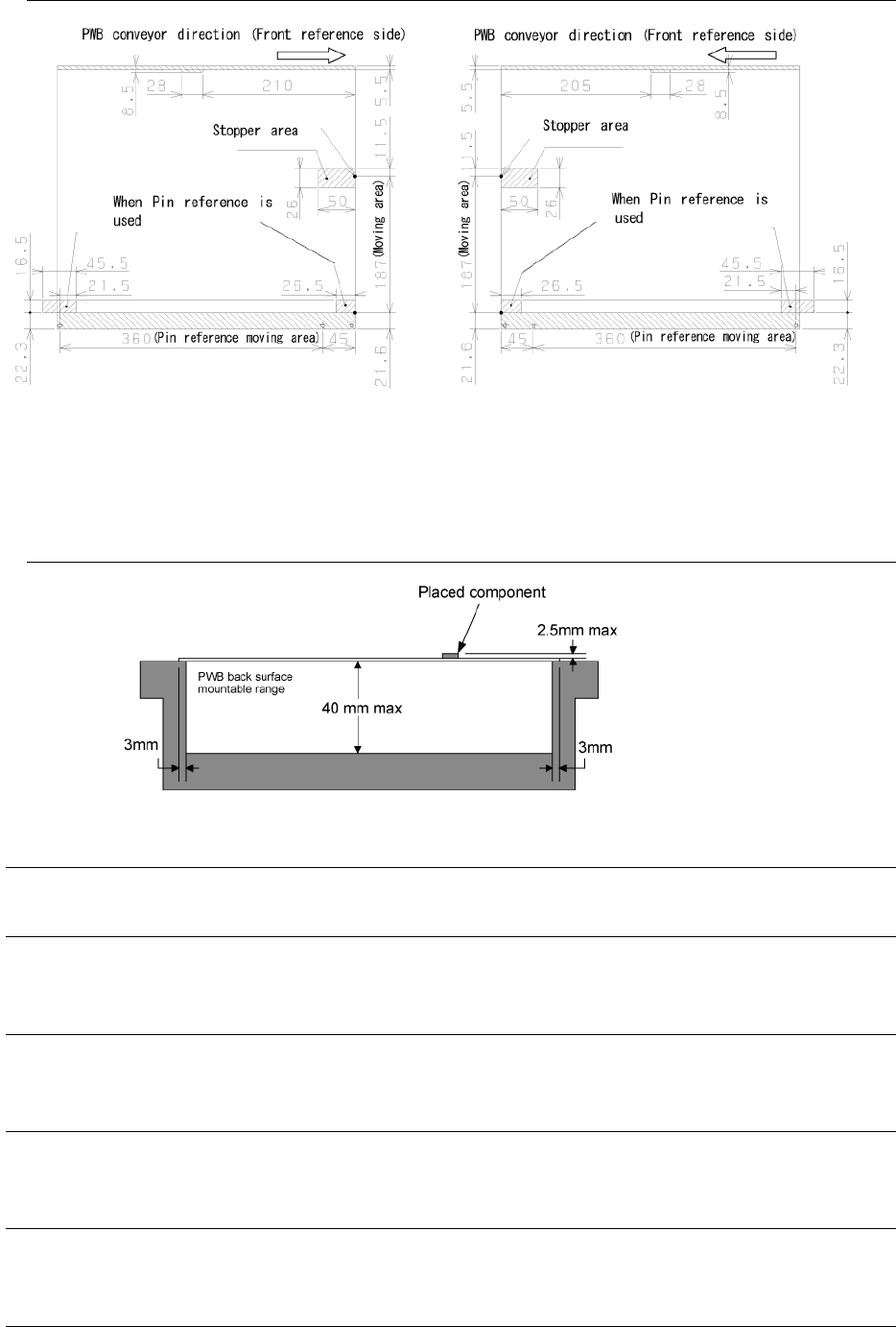
4.4.4.2 Bottom surface of PWB
Figure 3 Bottom surface of PWB
(Hatched portion: support pin non-installable range)
* Note: When the PWB conveyor direction is the rear reference side, direction is symmetrically
up and down to the above figure.
4.4.4.3 Allowable component height & back surface handling height
Figure 4 Allowable component height & back surface handling height
4.4.5 PWB transport reference
Front reference and rear reference (factory setting)
4.4.6 Allowable value of PWB warp
0.2 mm or less per 50 mm and 1 mm or less for both upper warp and lower warp (conforming to
JIS B 8461)
4.4.7 PWB clamping method
The front end and rear end of PWB are clamped on the conveyor rail on the fixed side
and moving side on a basis of the top surface of PWB.
4.4.8 Background transporting function
The background transporting function permits executing the transport idle mode in the
head or X-Y servo-free status or in the unfinished status of home-return.
4.4.9 PWB width alignment method
Standard: Manual alignment method using a crank handle
Option: Auto alignment method using motors
4.4.10 PWB buffer
One PWB buffer is provided on each of the loading side and unloading side.