KD-2077_SPE_EN.pdf - 第15页
11 4.5 PWB Positioning 4.5.1 P W B posi tioning ref erence S tan dard: Shap e referenc e Option: P in reference 4.5.2 P W B rec ognition visual f ield 6.3 mm (ca mera visua l field range) Figure 5 PWB recogniti on visual…
10
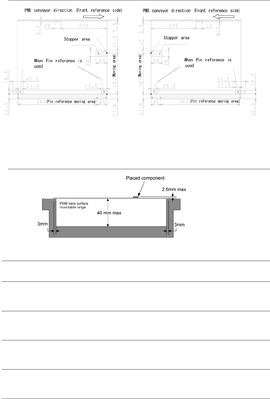
4.4.4.2 Bottom surface of PWB
Figure 3 Bottom surface of PWB
(Hatched portion: support pin non-installable range)
* Note: When the PWB conveyor direction is the rear reference side, direction is symmetrically
up and down to the above figure.
4.4.4.3 Allowable component height & back surface handling height
Figure 4 Allowable component height & back surface handling height
4.4.5 PWB transport reference
Front reference and rear reference (factory setting)
4.4.6 Allowable value of PWB warp
0.2 mm or less per 50 mm and 1 mm or less for both upper warp and lower warp (conforming to
JIS B 8461)
4.4.7 PWB clamping method
The front end and rear end of PWB are clamped on the conveyor rail on the fixed side
and moving side on a basis of the top surface of PWB.
4.4.8 Background transporting function
The background transporting function permits executing the transport idle mode in the
head or X-Y servo-free status or in the unfinished status of home-return.
4.4.9 PWB width alignment method
Standard: Manual alignment method using a crank handle
Option: Auto alignment method using motors
4.4.10 PWB buffer
One PWB buffer is provided on each of the loading side and unloading side.
11
4.5 PWB Positioning
4.5.1 PWB positioning reference
Standard: Shape reference
Option: Pin reference
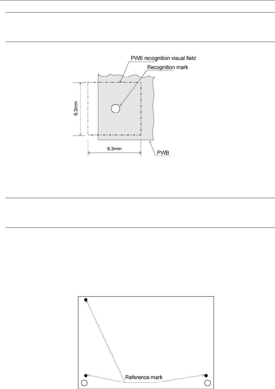
4.5.2 PWB recognition visual field
6.3 mm (camera visual field range)
Figure 5 PWB recognition visual field
4.5.3 Window size
The window size is variable up to 6.3 mm. However, secure a clearance around the recognition
mark.
4.5.4 Recognition mark correction method
The reference marks provided at 2 or 3 positions (Note) are used for positional correction of the
whole PWB. When the marks at 2 positions are detected, the position offset, angle offset, and
PWB expansion/contraction of the whole PWB are corrected. When the 3 marks at 3 positions are
detected, the PWB XY angle offset is additionally corrected.
Note: The positions are optional. Regarding the reference marks at 3 positions, however, these 3
marks must not be aligned on a single straight line. (It is recommended that marks are arranged
at the 4 corners of PWB.)
Figure 6 Reference marks
12
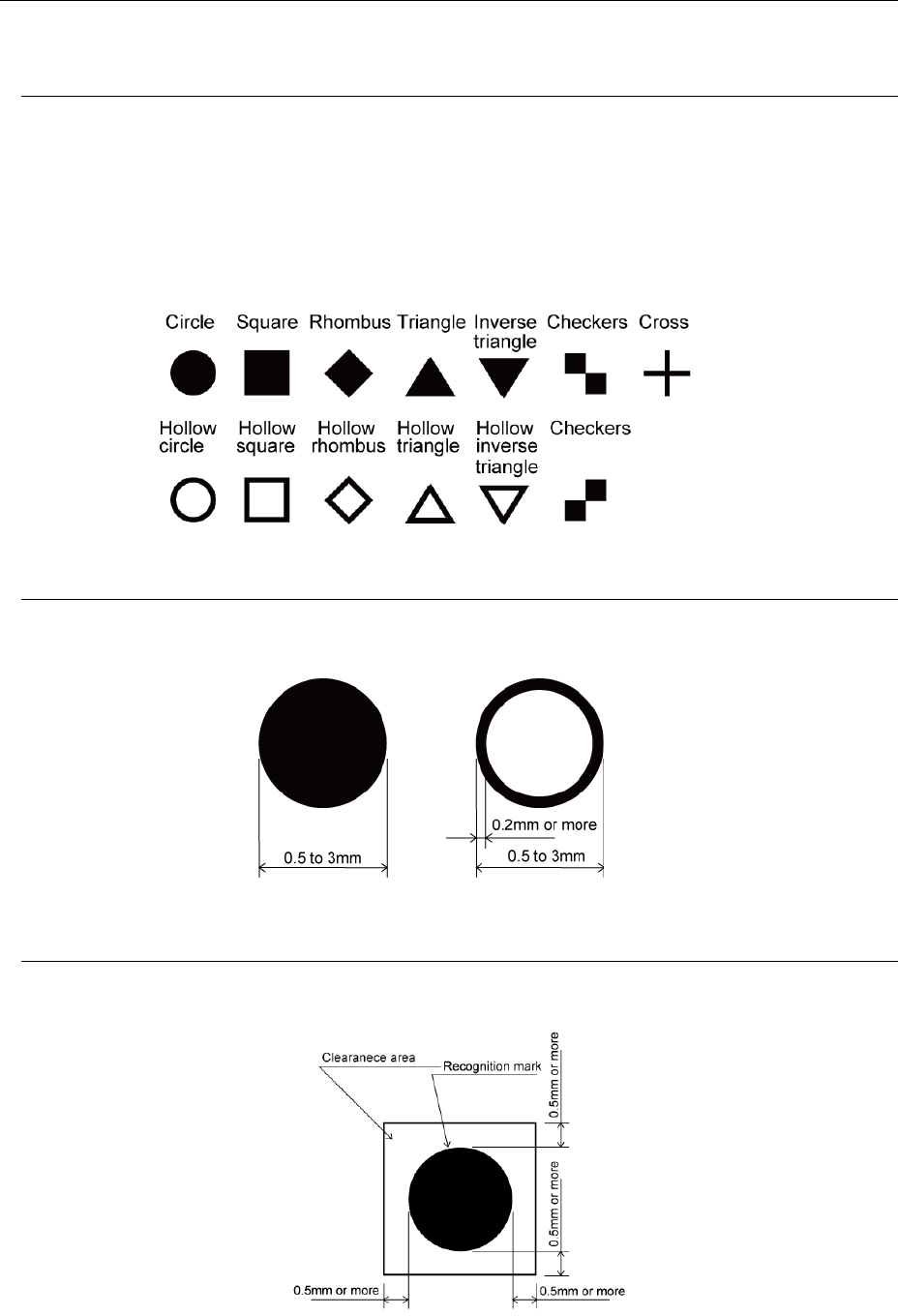
4.5.5 Recognition mark shapes
The recognition marks shall conform to EIAJ ET-7302 "Recognition Marks for Surface Mounting
PWB."
4.5.5.1 Shapes
• The standard marks shall be 13 types shown in "Figure 7 Recognition Mark Shapes."
• Marks other than "Figure 7 Recognition Mark Shapes", the user prepares templates and they
can be recognized by pattern matching.
Note 1: There shall be no patterns of similar shapes except the target mark shapes in the
visual field. Enough contrast shall be obtained.
• Regarding the triangles, checkers, and user's templates, their shapes rotated in a 90-degree
arc can also be recognized.
Figure 7 Recognition mark shapes
4.5.5.2 Size and tolerance
The external size shall be 0 5 mm to 3.0 mm and the tolerance shall be ±10% or less.
For hollow shapes, the line width of the fringe shall be 0.2 mm or more.
Figure 8 Size and tolerance of each recognition mark
4.5.5.3 Clearance
In the periphery of each recognition mark, secure at least 0.5 mm of space in which no
conductor pattern, solder resist or marking exists, from the outer periphery of the recognition
mark.
Figure 9 Clearance for recognition mark