KD-2077_SPE_EN.pdf - 第23页
19 7 .2.2 In put/outpu t signal i nterface Figure 13 S ignal interface and connec tion terminals 7 .2.3 S peci fication o f connecti on cable The connect ion cable shal l conform to JIS B 8438 I ndustrial Robot - Electri…
18
7 Interface
7.1 Mechanical Interface
7.1.1 PWB conveyor height
900 ± 20 mm
950 ± 20 mm (option)
7.2 Electrical Interface
7.2.1 Types and meanings of electric signals
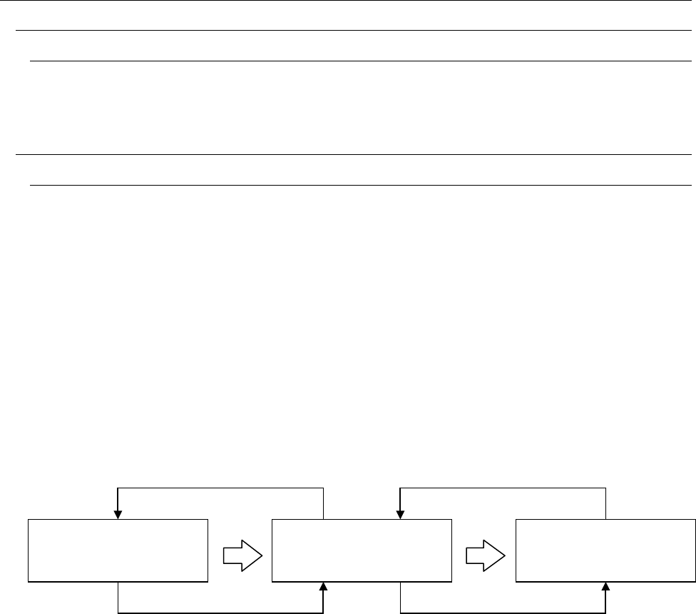
The concept of electric signal connections between this system and the opposite machine is
shown in “Figure 12 Conceptual diagram of electric signal connections.” In Figure 12, the electric
signals of ① and ② between this system and the upper-side equipment and the electric signals of
③ and ④ between this system and the lower-side equipment are shown below.
a) The electric signal ① is called carry-out request input signal (or board available IN)and
receives a PWB carry-out request from the upper equipment.
b) The electric signal ② is called carry-out enable output signal (or ready OUT) and causes the
upper-side equipment to carry out a PWB.
c) The electric signal ③ is called carry-out request output signal (or board available OUT) and
asks the lower-side equipment to carry out a PWB.
d) The electric signal ④ is called carry-out enable input signal (or ready IN) and receives PWB
carry-out permission from the lower-side equipment.
② ④
① ③
Figure 12 Conceptual diagrams of electric signal connections
Upper-side equipment
Lower-side equipment
This system
19
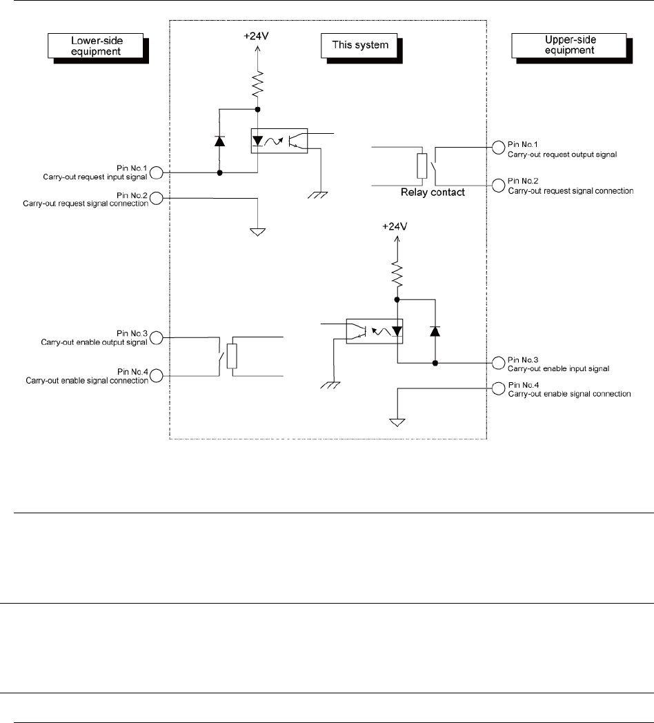
7.2.2 Input/output signal interface
Figure 13 Signal interface and connection terminals
7.2.3 Specification of connection cable
The connection cable shall conform to JIS B 8438 Industrial Robot - Electric Equipment.
The cable length shall be 10 m or less.
7.3 Data Interface
LAN (10/100BASE)
2 ports equivalent to USB 2.0
These ports connect FDD, CD-ROM, etc. as data interface. (Both are options.)
7.4 Utility Connection
7.4.1 Piping joint
One-touch type piping joint plug for a φ8 x φ2 hose

20
8 Safety Specifications
8.1 Standard Specifications
8.1.1 Emergency stop
An emergency stop is performed by emergency stop button. When the emergency stop switch is
pressed, each axis is stopped immediately and the driving power supply of the servo motor is shut
off.
8.1.2 Safety cover
A cover is provided on the front side of the machine. The open/close status is detected by cover
open switch. When the cover is opened, the continuous operation is temporarily stopped. With the
safety cover open, the machine cannot be operated.
8.2 CE mark Specification
The CE mark specification is not available.
9 Maintenance Specifications
9.1 Troubleshooting
The improved help function can find out an abnormal status caused by any factor and a
recovering method to return to the normal status.
9.2 MTBA Display Function
This function calculates and displays the mean time interval time (MTBA) from a short stop
occurring during production to the next short stop.
10 Reliability Specifications
10.1 Service Life of the System
Seven years. However, consumables and the following parts are excluded. (For details, please
ask to JUKI Sales dept. )
• Plastic rail
• Bear cables assembly
• Sensor
• Camera
• Solenoid valve
• Air cylinder
• Air filter element
• Gas spring
• CD-ROM
Calculation standard for service life
22 hours/day
300 days/year
22 x 300 x 7 = 46,200 hours/7 years