KD-2077_SPE_EN.pdf - 第4页
5.1.1 Ba d mark rea der ................................................................................................ . 14 5.1.2 Di spensing diameter recog nition u nit (with a blank run function ) ...................…
Table of contents
1 Overview ........................................................................................................................... 1
2 Features............................................................................................................................ 2
3 System Configuration ....................................................................................................... 3
4 Specifications .................................................................................................................... 4
4.1 Equipment Specifications ............................................................................................ 4
4.1.1 Power supply specifications .................................................................................. 4
4.1.2 Rated apparent power .......................................................................................... 4
4.1.3 Air pressure .......................................................................................................... 4
4.1.4 Maximum air consumption .................................................................................... 4
4.1.5 Operating environmental conditions ..................................................................... 4
4.1.6 Transport and storage environmental conditions .................................................. 4
4.1.7 External Dimensions ............................................................................................. 5
4.1.8 Mass of the main body.......................................................................................... 5
4.1.9 Noise .................................................................................................................... 5
4.2 Dispensing Head Unit ................................................................................................. 6
4.2.1 Dispensing time .................................................................................................... 6
4.2.2 Dispensing accuracy (X,Y or θ) ............................................................................ 6
4.2.3 Resolution ............................................................................................................. 7
4.2.4 Dispensing angle setting ....................................................................................... 7
4.2.5 Applicable syringe ................................................................................................. 7
4.2.6 Applicable needles ................................................................................................ 7
4.2.7 Discharge needles ................................................................................................ 7
4.2.8 Residual amount detecting function ...................................................................... 7
4.2.9 Air volume correcting function ............................................................................... 7
4.2.10 Temperature regulating function ......................................................................... 7
4.3 Recommended Glues ................................................................................................. 8
4.4 Target PWB ................................................................................................................. 8
4.4.1 PWB transporting direction ................................................................................... 8
4.4.2 PWB dimensions .................................................................................................. 8
4.4.3 PWB mass ............................................................................................................ 8
4.4.4 PWB parameter limits ........................................................................................... 9
4.4.5 PWB transport reference .................................................................................... 10
4.4.6 Allowable value of PWB warp ............................................................................. 10
4.4.7 PWB clamping method ....................................................................................... 10
4.4.8 Background transporting function ....................................................................... 10
4.4.9 PWB width alignment method ............................................................................. 10
4.4.10 PWB buffer ....................................................................................................... 10
4.5 PWB Positioning ....................................................................................................... 11
4.5.1 PWB positioning reference ................................................................................. 11
4.5.2 PWB recognition visual field ............................................................................... 11
4.5.3 Window size ....................................................................................................... 11
4.5.4 Recognition mark correction method .................................................................. 11
4.5.5 Recognition mark shapes ................................................................................... 12
5 Standard functions and Options ...................................................................................... 14
5.1 Standard functions .................................................................................................... 14
5.1.1 Bad mark reader ................................................................................................. 14
5.1.2 Dispensing diameter recognition unit (with a blank run function) ........................ 14
5.2 Options ..................................................................................................................... 15
5.2.1 Auto PWB Width Alignment ................................................................................ 15
5.2.2 External Air Vent Unit .......................................................................................... 15
5.2.3 EPU .................................................................................................................... 15
5.2.4 UPS .................................................................................................................... 15
5.2.5 BMR .................................................................................................................... 15
5.2.6 Leak Breaker ...................................................................................................... 15
5.2.7 LCD touch panel ................................................................................................. 15
5.2.8 IS (Intelligent Shopfloor Solutions) : Production support system ........................ 15
5.2.9 JaNets : Production support system ................................................................... 16
6 Control System ............................................................................................................... 17
6.1 Storage method ..................................................................................................... 17
6.2 Production program capacity ................................................................................. 17
6.3 Pointing device ...................................................................................................... 17
6.4 Input/output data format ......................................................................................... 17
7 Interface .......................................................................................................................... 18
7.1 Mechanical Interface ................................................................................................. 18
7.1.1 PWB conveyor height ......................................................................................... 18
7.2 Electrical Interface .................................................................................................... 18
7.2.1 Types and meanings of electric signals .............................................................. 18
7.2.2 Input/output signal interface ................................................................................ 19
7.2.3 Specification of connection cable ........................................................................ 19
7.3 Data Interface ........................................................................................................... 19
7.4 Utility Connection ...................................................................................................... 19
7.4.1 Piping joint .......................................................................................................... 19
8 Safety Specifications ....................................................................................................... 20
8.1 Standard Specifications ............................................................................................ 20
8.1.1 Emergency stop .................................................................................................. 20
8.1.2 Safety cover ........................................................................................................ 20
8.2 CE mark Specification ............................................................................................... 20
9 Maintenance Specifications ............................................................................................ 20
9.1 Troubleshooting ........................................................................................................ 20
9.2 MTBA Display Function ............................................................................................ 20
10 Reliability Specifications ............................................................................................... 20
10.1 Service Life of the System ...................................................................................... 20
1
1 Overview
The appearance and basic structure of this system are based on KE-2070/2080, and
Network control can be exerted through Ethernet.
Though the previous model (KD-775) is supported by DOS as OS (basic software), the
KD-2077 adopts Windows XP as OS to greatly improve the operability.
* The needle and production program data that are used in the KD-775 are available in common.
Additionally, the floor productivity operating system to be used with the JUKI mounters and dispensers,
allow you to manage the productions not only per line but also per floor. The IS manages and
optimizes the information and jobs for a whole manufacturing floor comprehensively to provide you
improved productivity, better manufacturing quality, and cost reduction.
* For the details of the floor productivity operating system, please refer to the functional specification
of each system.
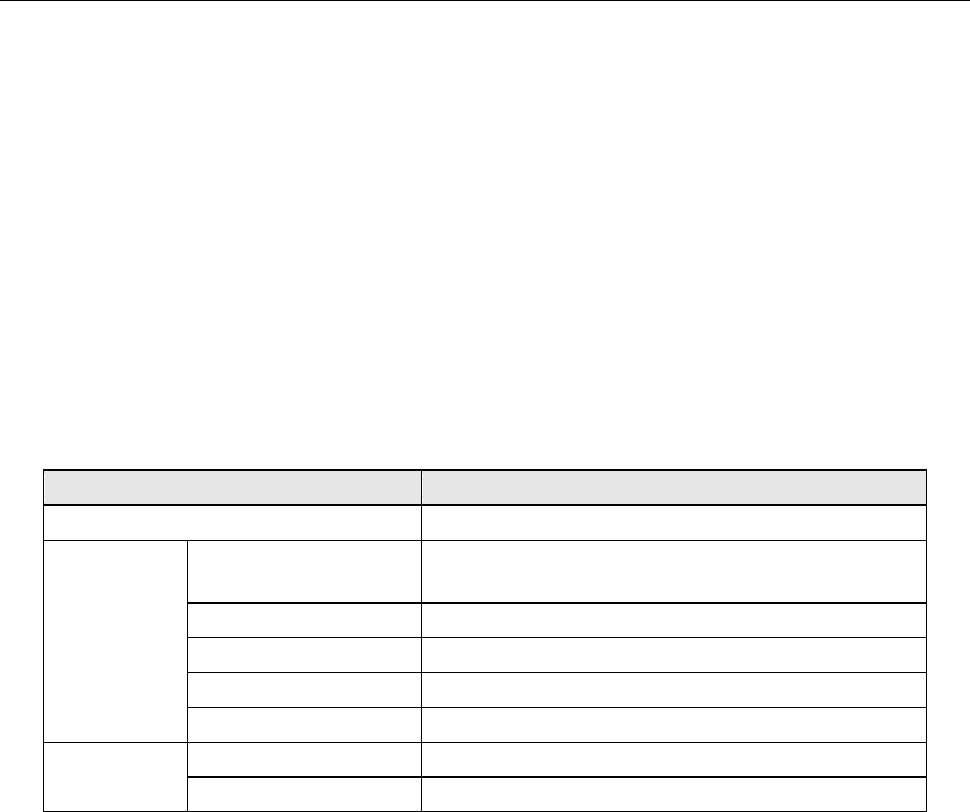
PWB Specifications and Configuration
KD-2077
Language used
Japanese, English, and Chinese
PWB
specifications
PWB dimensions
Minimum dimensions (L x W): 50 x 30 mm (Note 1)
Maximum dimensions (L x W): 410 x 360 mm
PWB thickness
0 4 to 4.0 mm
Transport flow direction
Flow to the right and flow to the left
Transport reference
Front reference and rear reference
Transport height
900mm ± 20mm and 950mm ± 20mm (option)
Configuration
Head configuration
1 head
Number of syringes
3 (30cc syringes)
Note 1: 50 x 50 mm when the auto PWB width alignment function is provided