KD-2077_SPE_EN.pdf - 第22页
18 7 Interf ace 7 .1 Mechanical Inte rface 7 .1.1 P W B c onveyor height 900 ± 20 mm 950 ± 20 mm (option) 7 .2 Elec trical Inter face 7 .2.1 T ypes and meaning s of electr ic signal s The concept of electric signal con n…

17
6 Control System
6.1 Storage method
The production program can be stored in a SSD or floppy disk.
The production control information can be stored in SSD.
* The SSD is a drive unit (solid state drive) using a flash memory as a storage medium on
behalf of HDD.
6.2 Production program capacity
Maximum number of steps per circuit: 3,000 steps
Maximum number of circuits per PWB: Number of matrix circuits 1200 and Number of
non-matrix circuits 200
Maximum number of steps per PWB: 10,000 steps
Maximum number of component data: 240
Maximum number of dispensing data: 240
Maximum number of registered marks: 1 set of BOC marks (2 or 3 pieces)
6.3 Pointing device
Mouse
Touch panel (option)
6.4 Input/output data format
The input/output of text format (XML format) is supported.
18
7 Interface
7.1 Mechanical Interface
7.1.1 PWB conveyor height
900 ± 20 mm
950 ± 20 mm (option)
7.2 Electrical Interface
7.2.1 Types and meanings of electric signals
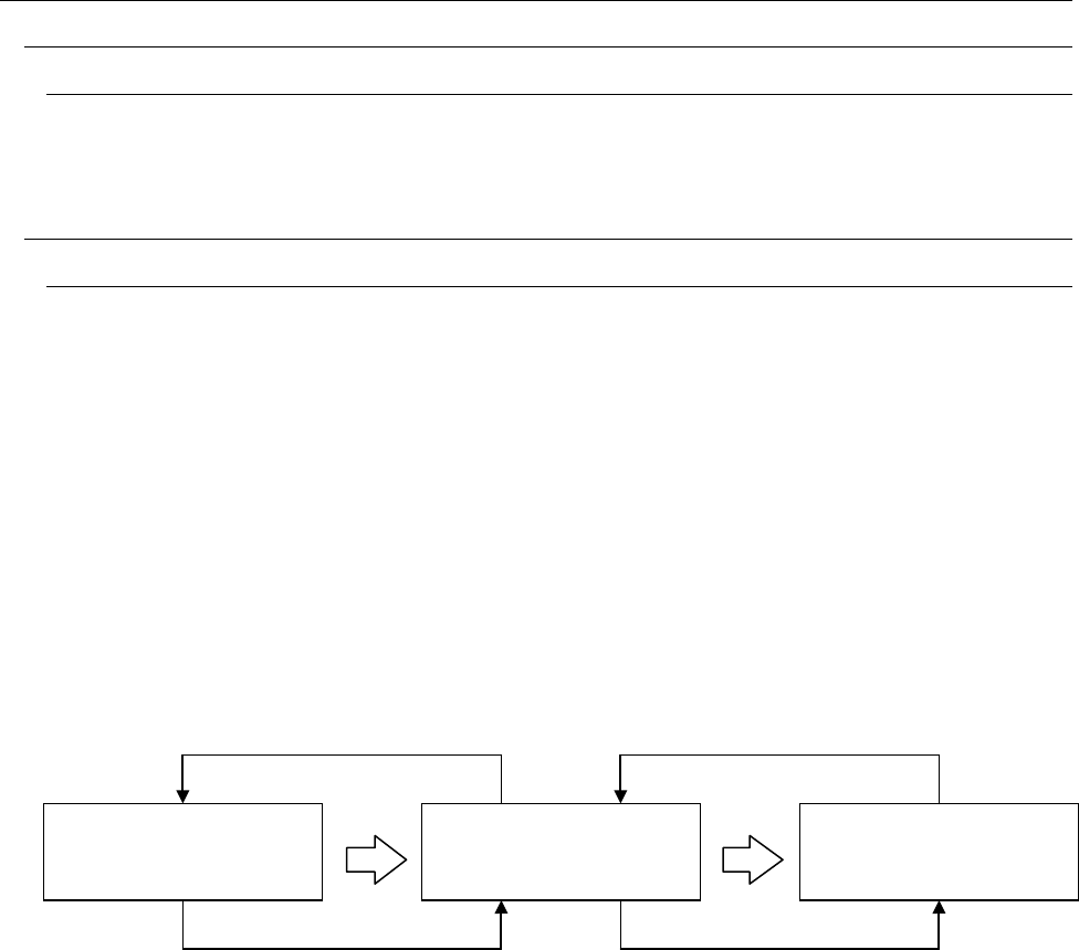
The concept of electric signal connections between this system and the opposite machine is
shown in “Figure 12 Conceptual diagram of electric signal connections.” In Figure 12, the electric
signals of ① and ② between this system and the upper-side equipment and the electric signals of
③ and ④ between this system and the lower-side equipment are shown below.
a) The electric signal ① is called carry-out request input signal (or board available IN)and
receives a PWB carry-out request from the upper equipment.
b) The electric signal ② is called carry-out enable output signal (or ready OUT) and causes the
upper-side equipment to carry out a PWB.
c) The electric signal ③ is called carry-out request output signal (or board available OUT) and
asks the lower-side equipment to carry out a PWB.
d) The electric signal ④ is called carry-out enable input signal (or ready IN) and receives PWB
carry-out permission from the lower-side equipment.
② ④
① ③
Figure 12 Conceptual diagrams of electric signal connections
Upper-side equipment
Lower-side equipment
This system
19
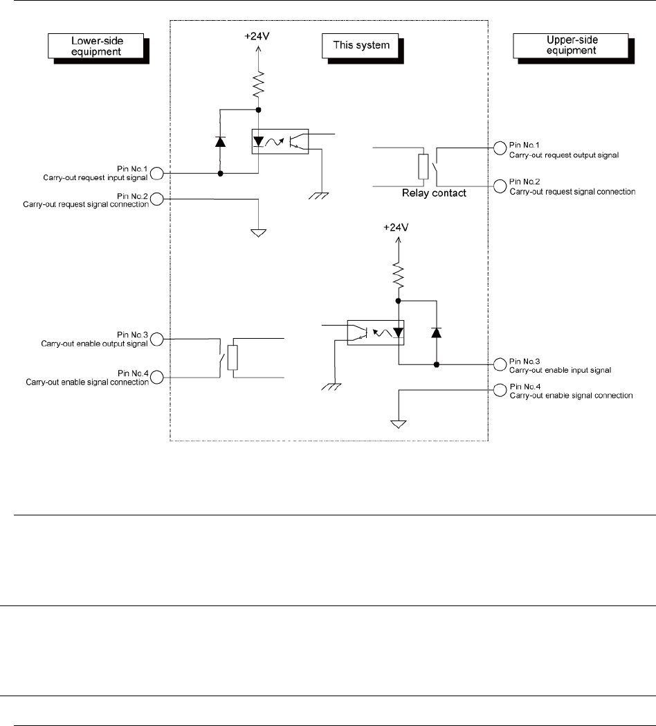
7.2.2 Input/output signal interface
Figure 13 Signal interface and connection terminals
7.2.3 Specification of connection cable
The connection cable shall conform to JIS B 8438 Industrial Robot - Electric Equipment.
The cable length shall be 10 m or less.
7.3 Data Interface
LAN (10/100BASE)
2 ports equivalent to USB 2.0
These ports connect FDD, CD-ROM, etc. as data interface. (Both are options.)
7.4 Utility Connection
7.4.1 Piping joint
One-touch type piping joint plug for a φ8 x φ2 hose