00198521-01_UM_LDU_E_EN.pdf - 第21页
3 Function description and structure 3.2 Structure User Manual SIPLACE Linear Dipping Unit E 12/2018 21 3.2.4 Dip plate 1. Dip plate 2. Cavity The following dip plates are available for the LDU E: Item number Depth of ca…
3 Function description and structure
3.2 Structure
20 User Manual SIPLACE Linear Dipping Unit E 12/2018
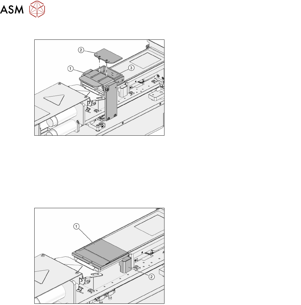
3.2.2 Squeegee
1. Downholder
2. Cover
3. Flux tank
The removable cover of the flux tank reduces any vaporization or drying out of the flux. The down-
holder holds the flux tank in the correct position. By pressing on the downholder the flux tank can
easily be removed.
The flux tanks available so far are still compatible with the LDU:
●
Standard tank [03060794-xx]
●
Small tank [03062326-xx]
3.2.3 Park plate and drip tray
1. Park plate
2. Drip tray
The park plate is held in place by permanent magnets. The shape of the drip tray is asymmetric so
that it cannot be fitted wrongly. Two sensors on the base determine whether a park plate or a drip
tray is fitted.
3 Function description and structure
3.2 Structure
User Manual SIPLACE Linear Dipping Unit E 12/2018 21
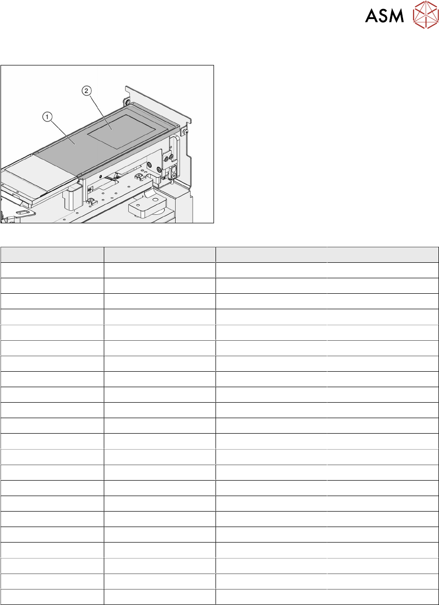
3.2.4 Dip plate
1. Dip plate
2. Cavity
The following dip plates are available for the LDU E:
Item number Depth of cavity [µm] Item number Depth of cavity [µm]
03059408-xx - 03072948-xx 200
03063053-xx 20 03072958-xx 210
03078159-xx 25 03068486-xx 220
03063054-xx 30 03064360-xx 230
03063055-xx 40 03069330-xx 240
03070690-xx 45 03074835-xx 250
03063056-xx 50 03074808-xx 260
03063057-xx 60 03074844-xx 270
03063058-xx 70 03065213-xx 280
03066566-xx 75 03074850-xx 290
03063059-xx 80 03072530-xx 300
03063060-xx 90 03074853-xx 310
03063061-xx 100 03069331-xx 320
03072107-xx 110 03074856-xx 330
03069323-xx 120 03074891-xx 340
03072883-xx 130 03074894-xx 350
03072903-xx 140 03063106-xx 360
03072913-xx 150 03074899-xx 370
03072916-xx 160 03074904-xx 380
03072919-xx 170 03074909-xx 390
03072923-xx 180 03069332-xx 400
03072925-xx 190
3 Function description and structure
3.2 Structure
22 User Manual SIPLACE Linear Dipping Unit E 12/2018
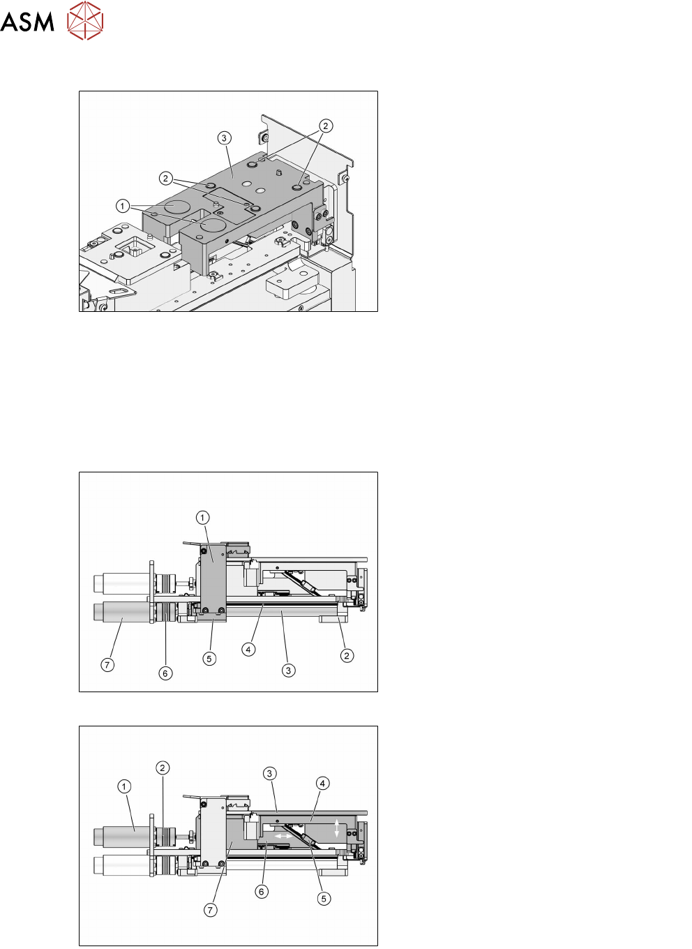
3.2.5 Dip stroke plate
1. Electromagnets
2. Permanent magnets
3. Dip stroke plate
The dip plate is held in place on the dip stroke plate by four permanent magnets. Two electromag-
nets are used for additional fixing and check whether a dip plate is fitted. The electromagnets de-
tect changes in the distance between dip plate and lift unit. This will be the case when the dip plate
gets stuck to the park plate during the downwards movement.
3.2.6 Axes
The LDU has two drive axes.
The squeegee axis moves the squeegee forwards and backwards.
1. Squeegee
2. Front bearing block
3. Spindle
4. Guide rail
5. Rear bearing block
6. Coupling
7. Motor
The lift axis moves the dip plate up and down:
1. Motor
2. Coupling
3. Dip plate
4. Dip stroke plate
5. Guidance
6. Slide
7. Bearing block (base of park plate)
The maximum lift of the lift axis is -8.5mm to +22mm (mechanical stoppers). The basic position
(determined by an inductive switch) is at -7.5mm. The squeegee is positioned at 0mm. The dip
position is at +17.5mm. Squeegee and dip position are determined by the pulse generator of the
motor.