00198521-01_UM_LDU_E_EN.pdf - 第45页
4 Operation 4.6 Performing a height measurement User Manual SIPLACE Linear Dipping Unit E 12/2018 45 Definitions ● Measuring point 1: reference point. ● Absolute height [µm]: the measured height of the respective measuri…
4 Operation
4.6 Performing a height measurement
44 User Manual SIPLACE Linear Dipping Unit E 12/2018
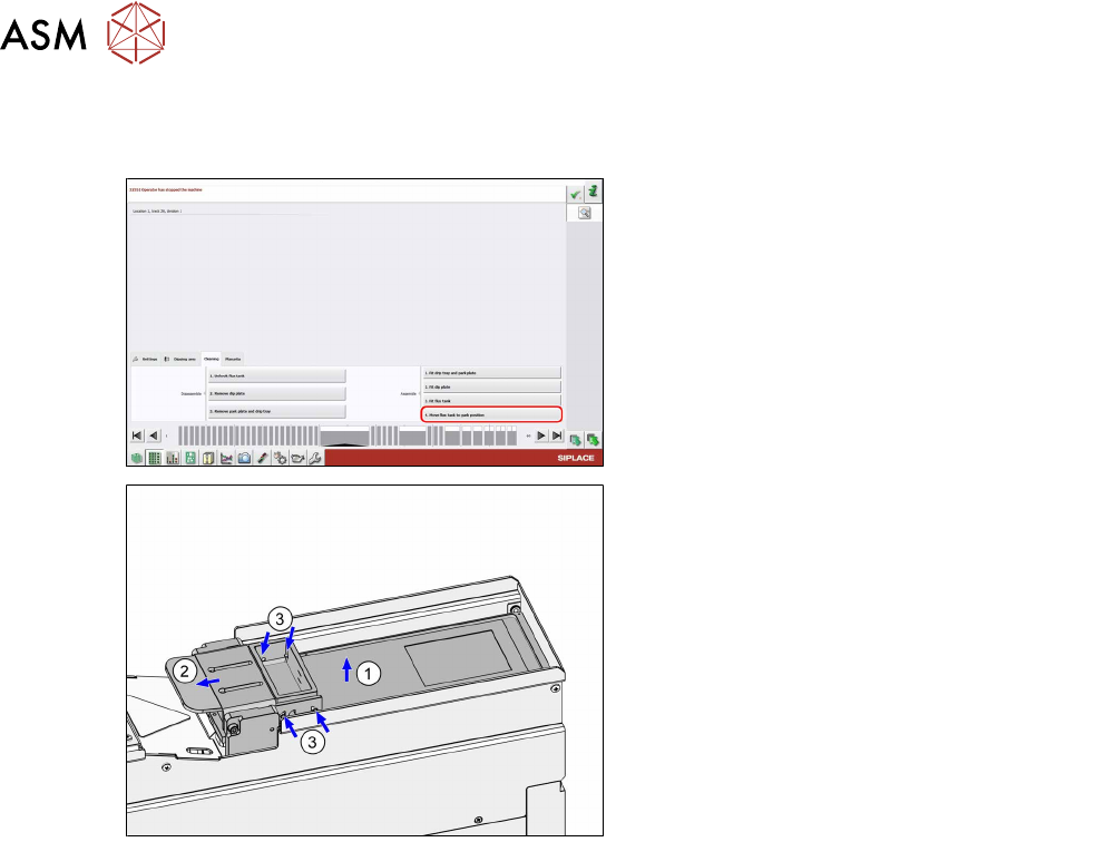
Moving the flux tank to the park position
Prerequisites: The park plate and the dip plate are fitted.
► Click on the Move flux tank to park posi-
tion button.
(1) The LDU moves the lift axis to the zero posi-
tion while the downholder locks the flux tank.
(2) The LDU moves the squeegee back over the
park plate.
► (3) Ensure that the four pins of the flux
tank engage correctly in the retaining
clamp of the downholder.
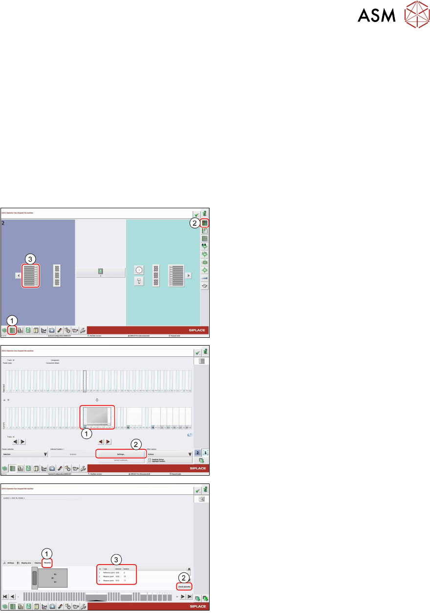
4.6 Performing a height measurement
To ensure that the components can be dipped into the medium over the entire dipping area, it is
important that the dipping area is not tilted. You therefore need to align the LDU parallel to the
gantry or to the placement head of the placement machine. The LDU has two adjustment screws
for this purpose. The correct position of the cavity can be checked with the help of the measure-
ment run in the station software.
The measurement run sets the dip plate parallel to the gantry. It does NOT determine the level of
the dip plate compared to the ground. It is therefore important that the machine in which the LDU is
used is standing absolutely level. If the machine is not level and the dip plate is aligned parallel to
the gantry, the dip plate will then not be level in relation to the ground.
Height measurement procedure
The placement head moves over the first measuring point in the cavity of the dip plate. After this,
the Z-axis moves slowly downwards until the nozzle springs into place and the Z-axis sensor re-
ports that the nozzle is now down on the dip plate. The Z-axis then moves up again. The system
calculates the absolute height of the first measuring point.
The gantry now moves to the second measuring point. The Z-axis performs height measurement
again and now determines the relative height difference to the first measuring point. If the measure-
ment for the second measuring point is positive, measuring point 2 is higher than measuring point
1. If it is negative, this means that it is lower. If the relative measurement is zero, this means that
both measuring points are at the same height. The same procedure is applied to the third measur-
ing point.
4 Operation
4.6 Performing a height measurement
User Manual SIPLACE Linear Dipping Unit E 12/2018 45
Definitions
●
Measuring point 1: reference point.
●
Absolute height [µm]: the measured height of the respective measuring point.
●
Relative height [µm]: the deviation of the absolute height of measuring point 2 or 3 to the ab-
solute height of the reference point. This value is always 0 for the reference point.
Preconditions
► The placement machine must be exactly level to the ground.
► The cavity of the dip plate must be free of flux.
► There must be a nozzle on the placement head.
Performing a height measurement
► In the station software, select the Setup
view(1) and then the Locations area (2).
► Select the Table (3) on which the LDU is
set up.
► Select the icon of the LDU(1).
► Click on the Settings... button (2).
► Select the Planarity tab(1).
► Click on the Check planarity button(2).
The machine will perform the measurement and
then show the values determined in the table
(3).
► Read the values.
●
The relative values for measuring points 2 and 3 are lower than +/- 50 μm: the LDU is set
correctly.
●
The relative values for measuring points 2 and 3 are greater than +/- 50 μm:
► Perform the following steps until the relative values for measuring points 2 and 3 are lower
than +/-50µm:
► Align the LDU (see 4.7 "Aligning" [}46]).
► Repeat the height measurement.
4 Operation
4.7 Aligning
46 User Manual SIPLACE Linear Dipping Unit E 12/2018
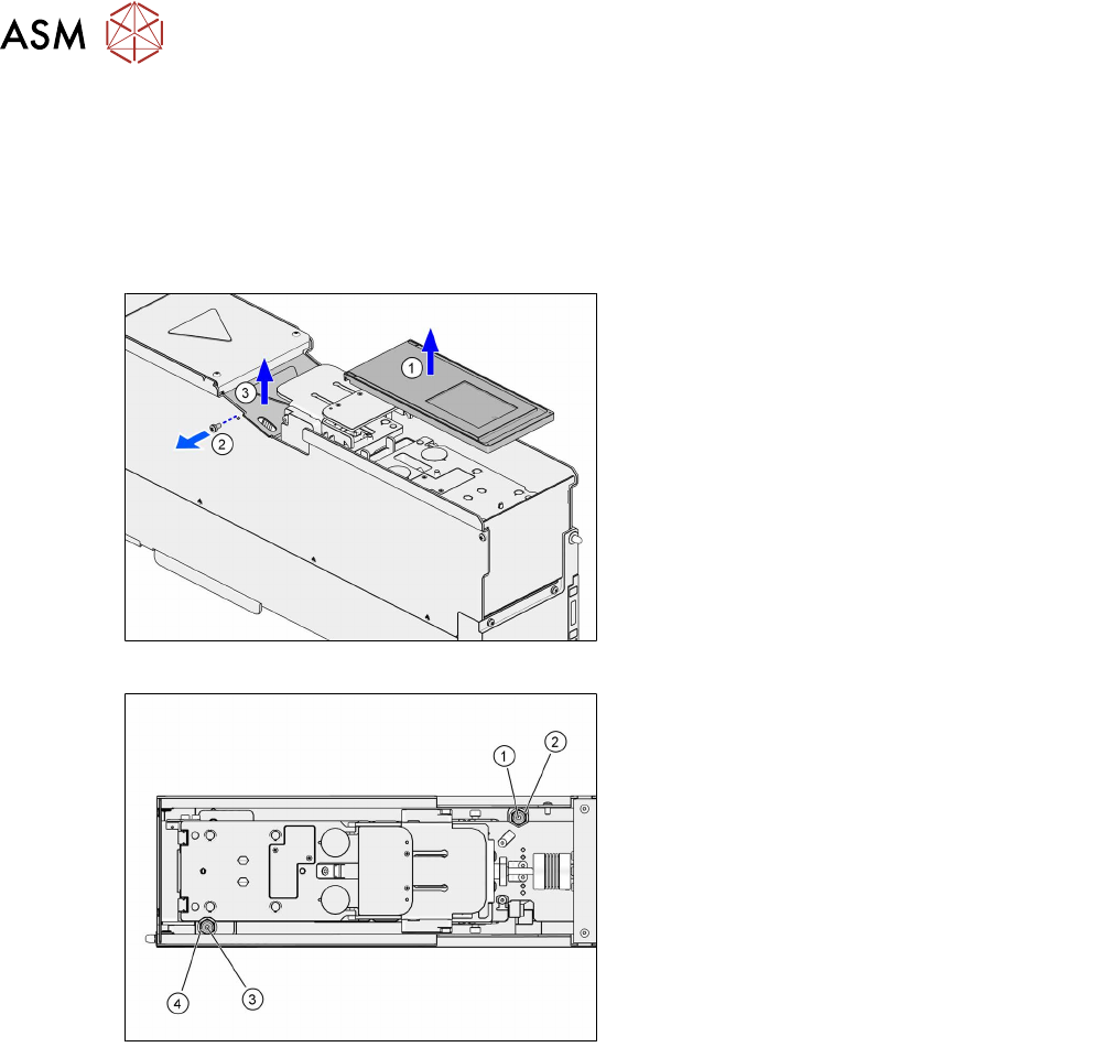
4.7 Aligning
You need the following tools to align the LDU:
●
Phillips screwdriver
●
Allen key 3 mm
●
Allen key 10 mm
► Lift off the dip plate(1).
► Remove the fastening screw of the coup-
ling cover(2).
► Lift off the coupling cover(3).
The screws for aligning the LDU are easily accessible from above:
1. Rear fixing screw (Allen screw 3mm)
2. Rear adjustment screw (Allen screw
10mm)
3. Front fixing screw (Allen screw 3mm)
4. Front adjustment screw (Allen screw
10mm)
Each of the two pairs consisting of fixing screw and adjustment screw is arranged concentrically.
► Loosen the two fixing screws (1) and (3) with an Allen key of size 3mm.
► Align the dip plate with the two adjustment screws (2) and (4) (Allen key 10 mm).
Rotating one of the adjustments screws clockwise will lift the dip plate at this position.
Rotating one of the adjustment screws counterclockwise will lower the dip plate at this position.
One revolution of the adjustment screws corresponds to lifting or lowering by 0.5mm.
► Tighten the two fixing screws (1) and (3) with a maximum torque of 0.75Nm.
► Fit the coupling cover.
► Fit the dip plate.