00198521-01_UM_LDU_E_EN.pdf - 第23页
3 Function description and structure 3.2 Structure User Manual SIPLACE Linear Dipping Unit E 12/2018 23 3.2.7 Leveling device The leveling device is based on a three-point support: one bearing ball and two adjustment scr…
3 Function description and structure
3.2 Structure
22 User Manual SIPLACE Linear Dipping Unit E 12/2018
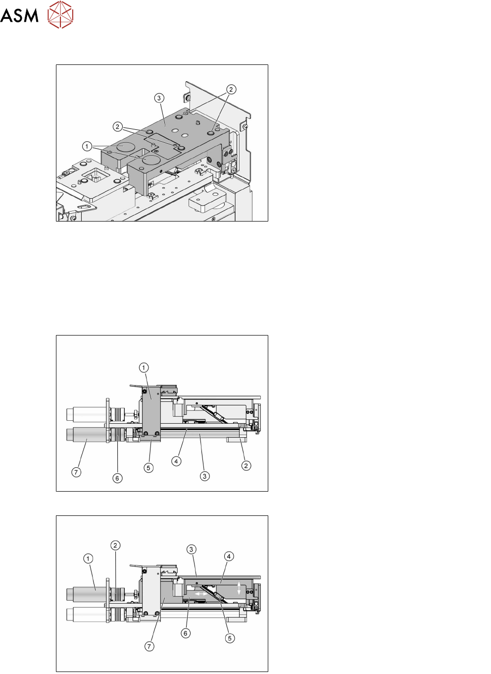
3.2.5 Dip stroke plate
1. Electromagnets
2. Permanent magnets
3. Dip stroke plate
The dip plate is held in place on the dip stroke plate by four permanent magnets. Two electromag-
nets are used for additional fixing and check whether a dip plate is fitted. The electromagnets de-
tect changes in the distance between dip plate and lift unit. This will be the case when the dip plate
gets stuck to the park plate during the downwards movement.
3.2.6 Axes
The LDU has two drive axes.
The squeegee axis moves the squeegee forwards and backwards.
1. Squeegee
2. Front bearing block
3. Spindle
4. Guide rail
5. Rear bearing block
6. Coupling
7. Motor
The lift axis moves the dip plate up and down:
1. Motor
2. Coupling
3. Dip plate
4. Dip stroke plate
5. Guidance
6. Slide
7. Bearing block (base of park plate)
The maximum lift of the lift axis is -8.5mm to +22mm (mechanical stoppers). The basic position
(determined by an inductive switch) is at -7.5mm. The squeegee is positioned at 0mm. The dip
position is at +17.5mm. Squeegee and dip position are determined by the pulse generator of the
motor.
3 Function description and structure
3.2 Structure
User Manual SIPLACE Linear Dipping Unit E 12/2018 23
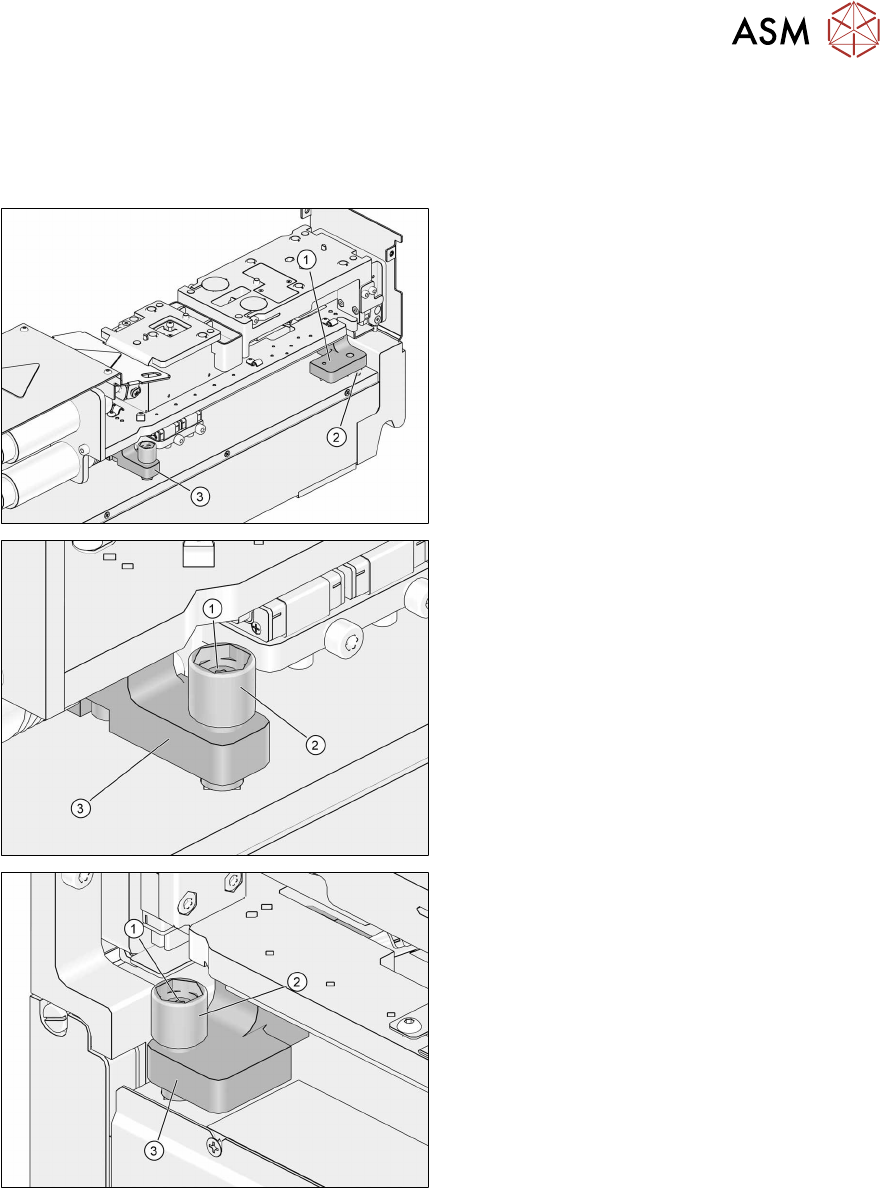
3.2.7 Leveling device
The leveling device is based on a three-point support: one bearing ball and two adjustment screws.
The front bearing block is located on the bearing ball and the front adjustment screw. The rear
bearing block is located on the rear adjustment screw.
1. Front bearing block
2. Bearing ball
3. Rear bearing block
1. Rear fixing screw
2. Rear adjustment screw
3. Rear bearing block
1. Front fixing screw
2. Front adjustment screw
3. Front bearing block
3 Function description and structure
3.2 Structure
24 User Manual SIPLACE Linear Dipping Unit E 12/2018
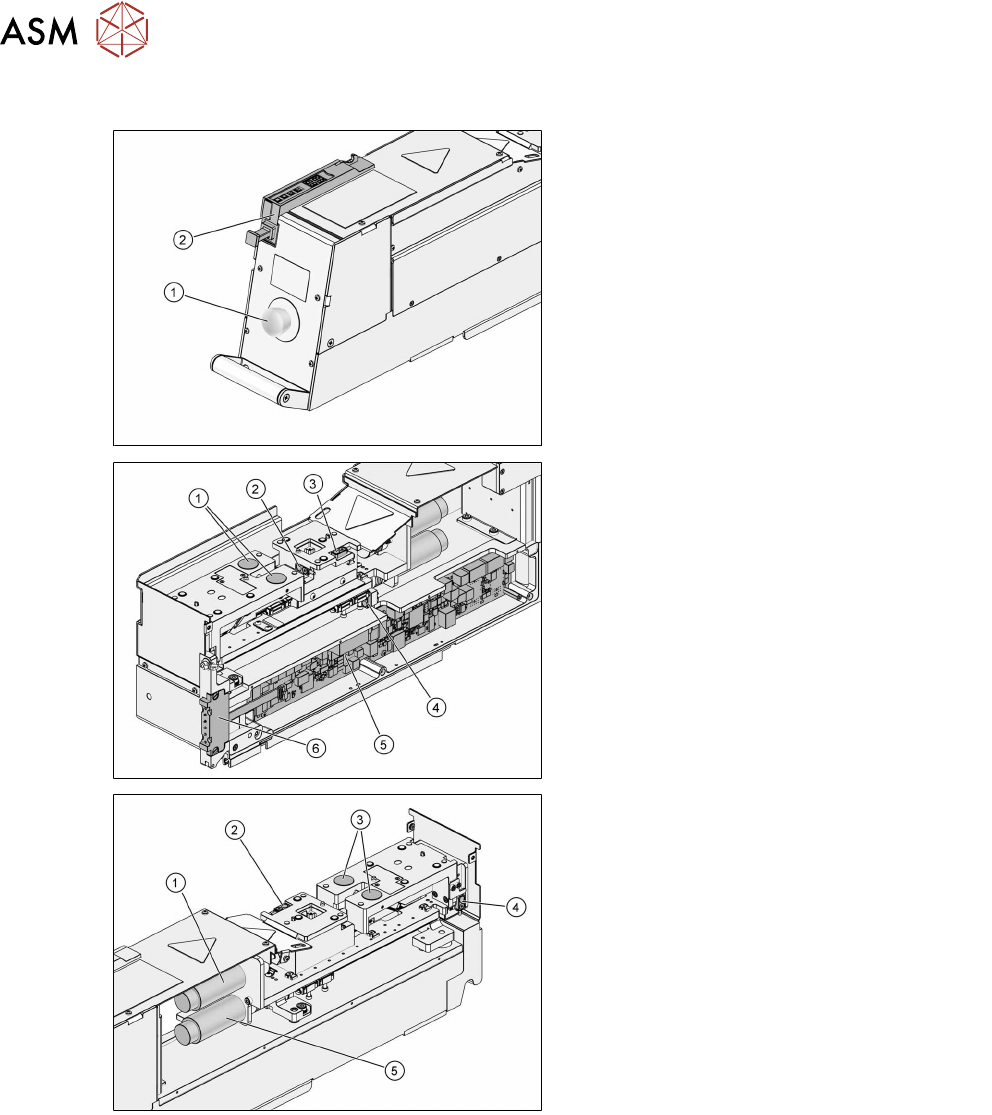
3.2.8 Electronics
1. Emergency stop button
2. Control unit
1. Electromagnets
2. Sensor for drip tray
3. Sensor for park plate
4. Position switch of squeegee axis
5. Control board
6. Spring contact area
1. Motor of lift axis
2. Sensor for park plate
3. Electromagnets
4. Position switch of lift axis
5. Motor of squeegee axis