00198521-01_UM_LDU_E_EN.pdf - 第31页
3 Function description and structure 3.3 Basic process User Manual SIPLACE Linear Dipping Unit E 12/2018 31 3.3.5 Squeegee speed The squeegee speed has a great influence on the surface of the flux after application. 1. T…
3 Function description and structure
3.3 Basic process
30 User Manual SIPLACE Linear Dipping Unit E 12/2018
3.3.3 Cicatrization time
Flux can consist of several different components. These are typically:
●
Colophony (solderability, adhesive force, cleanliness, pressure application)
●
Activator (solderability, reliability, product life, cleanliness)
●
Stabilizer (thixotropic stability, pressure application, contour stability)
●
Solvent (resistance behavior, adhesive force, viscosity)
The solvent in flux is water or alcohol based. These substances evaporate with time if the flux is
kept in an open tank.
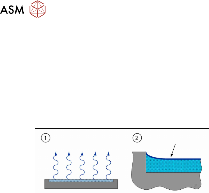
The LDU has a very thin layer of flux in the dip plate cavity. This means that the solvent can evap-
orate over a large surface (1). A thin skin then forms on the surface of the flux (2), the flux cica-
trizes. Inside this skin, the process properties of the flux differ from those in the remaining flux.
If longer standstill (inactive) times are expected during the production run can be expected, you can
set a cicatrization time. The LDU will then perform an application run after this period has expired.
The cicatrization time is set in the line software: 4.1.9 "Setting the cicatrization time of the
flux" [}38]
3.3.4 Viscosity and thixotropy
Some flux types have chemicals added to influence the viscosity. Some materials also change their
viscosity under pressure. Examples from everyday life include mayonnaise and ketchup. Mayon-
naise is very thick but thins out under pressure. Ketchup pours better from the bottle if it is shaken
first. The viscosity changes after the substance has been moved. These kinds of substances are
known as thixotropic.
Most substances increase their viscosity when cooler and reduce it when warmed.
The LDU provides a warming function. This helps to influence the viscosity of the flux before it is
used. During this warm-up cycle the LDU performs a number of squeegee processes which can be
set. This moves the flux and "warms" it up.
The warm-up cycle is started in the station software: 4.10 "Starting a warm-up cycle" [}48].
3 Function description and structure
3.3 Basic process
User Manual SIPLACE Linear Dipping Unit E 12/2018 31
3.3.5 Squeegee speed
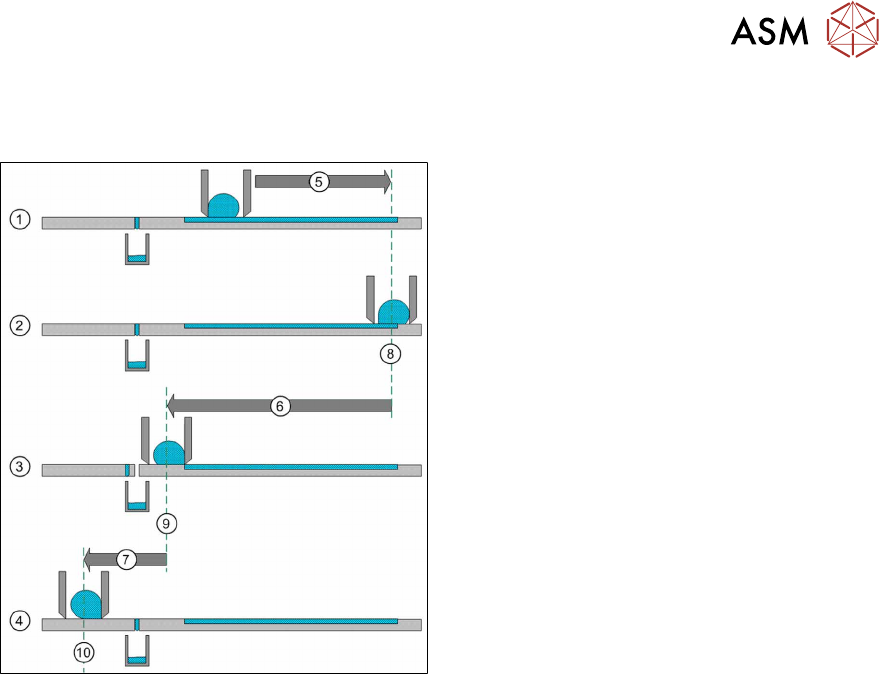
The squeegee speed has a great influence on the surface of the flux after application.
1. The squeegee axis moves with maximum
speed forward to the reverse position(5).
2. The squeegee axis is now in the reverse
position(8).
3. The squeegee axis moves with adjustable
squeegee speed over the cavity(6) back in
the acceleration position(9).
4. The squeegee axis moves with maximum
speed(7) back to the park position on the
park plate(10).
The squeegee speed is set in the line software: 4.1.10 "Setting the warm-up cycle and the squee-
gee speed" [}38].
The optimum squeegee speed for the flux used must be determined in tests. It is therefore useful to
use the following standard speeds as a starting point:
●
Flux = 200mm/s
●
Solder paste = 100mm/s
3 Function description and structure
3.3 Basic process
32 User Manual SIPLACE Linear Dipping Unit E 12/2018
3.3.6 Dip process and dwell time
The dip process in placement machines roughly consists of the following steps:
1. Pick component up from the relevant feeder module
2. Dip component in the flux
3. Check and center component with the Vision system
4. Place component on the board
The detailed dipping procedure (step 2) consists of the following steps:
1. The placement head moves with the component over the LDU to an unused part of the dip-
ping area. The placement head moves down until the component reaches the bottom of the
cavity.
2. The down sensor for the placement head starts a dwell time.
3. After the end of the dwell time, the placement head moves up again.
During the dwell time, the flux can coat the component on the parts which have been dipped into it.
The dwell time can be set in the line software: 4.1.5 "Setting the dip sequence and the dwell
time" [}35]. The correct dwell time must be determined through tests.
3.3.7 Creep distance
Depending on the viscosity of the flux used, it can be necessary to adjust the speed down or speed
up when dipping into the cavity. Components which get stuck in the flux of the cavity when the
nozzle moves up indicate that the speed up is too high. A speed down that is too high can lead to
uneven wetting of the component balls/bumps.
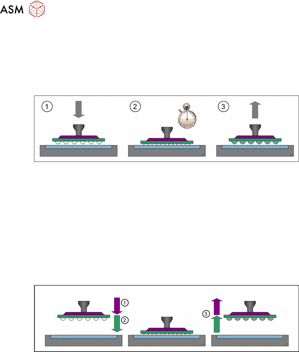
The distance between the surface of the cavity depth and the creep point is the creep distance.
(1) The placement head moves down with normal speed until it reaches the adjustable creep point
where it slows down to the adjustable speed down value.
(2) The placement head moves down with the speed down until it reaches the surface of the cavity
depth.
(3) The placement head moves up with the adjustable speed up until it reaches the creep point
where it accelerates to normal speed.
Creep point, speed down and speed up for each component and flux are set in the line software:
4.1.7 "Setting the creep distance" [}37].