00198521-01_UM_LDU_E_EN.pdf - 第51页
4 Operation 4.13 Logging off and removal User Manual SIPLACE Linear Dipping Unit E 12/2018 51 4.13 Logging off and removal The LDU E will be logged off, unlocked and removed from the placement machine like any E- feeder …
4 Operation
4.12 Refreshing the dipping medium
50 User Manual SIPLACE Linear Dipping Unit E 12/2018
4.12 Refreshing the dipping medium
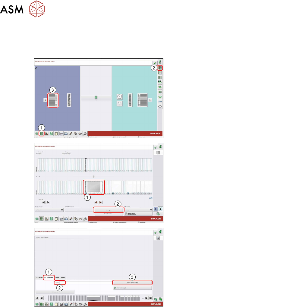
With the Refresh dipping medium function you can perform a set number of squeegee move-
ments to refresh the flux in the cavity.
► In the station software, select the Setup
view(1) and then the Locations area (2).
► Select the Table (3) on which the LDU is
set up.
► Select the icon of the LDU(1).
► Click on the Settings... button (2).
► Select the Dipping area tab (1).
► If required, enter the desired number of
squeegee movements to be performed in
the Cycles field.
► Click on the Refresh dipping medium
button (3).
The LDU performs the set number of squeegee
movements.
4 Operation
4.13 Logging off and removal
User Manual SIPLACE Linear Dipping Unit E 12/2018 51
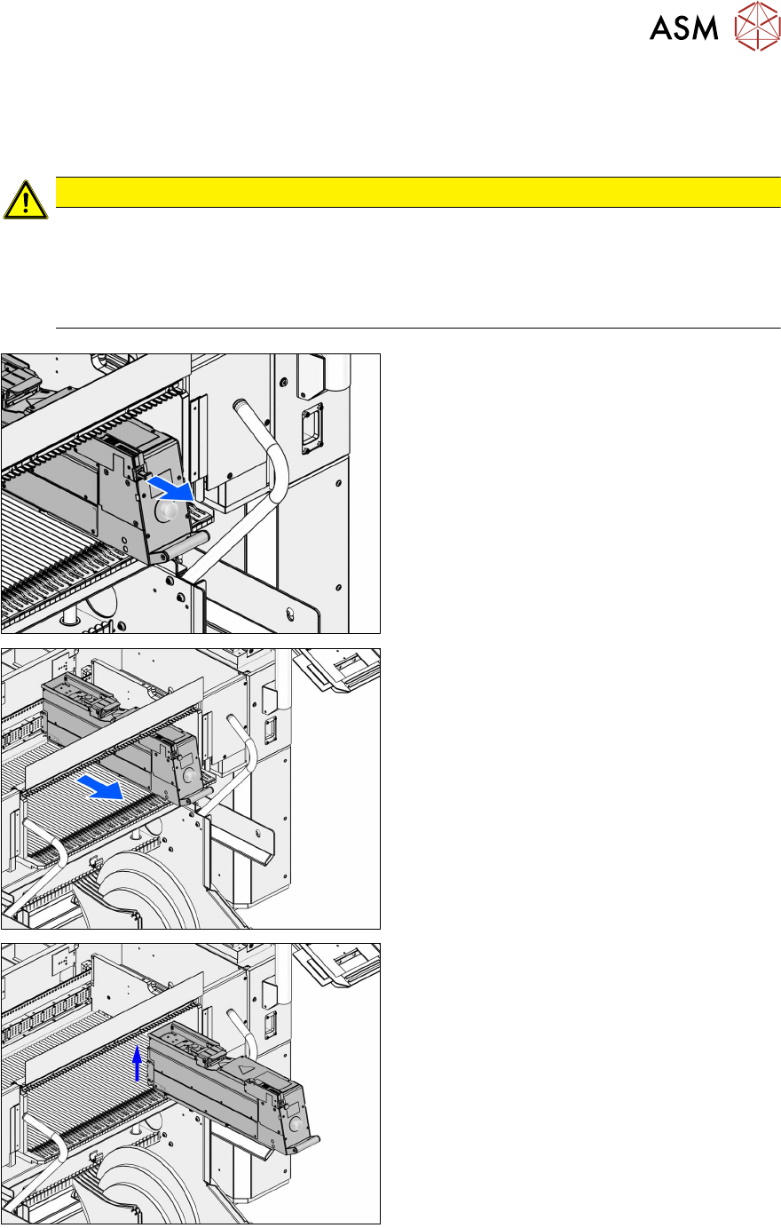
4.13 Logging off and removal
The LDU E will be logged off, unlocked and removed from the placement machine like any E-
feeder module.
CAUTION
Danger of tilting or falling down
The LDUE can tilt or fall down when handled incorrectly during removal from the
changeover table.
► When removing the LDUE hold it with both hands: take the gripper with one hand and
support the housing with the other hand (see chapter 4.2 "Handling" [}39]).
► Pull out the unlocking lever until you hear a
clicking sound.
► Carefully pull the LDU E backwards by the
handle.
► Remove the LDU E with both hands from
the changeover table.
4 Operation
4.14 Checking the layer thickness
52 User Manual SIPLACE Linear Dipping Unit E 12/2018
4.14 Checking the layer thickness
There are numerous measuring devices for paintshops and coating specialists on the market,
which are used to measure the layer thicknesses of paints, varnishes, pastes etc.
(wet film thickness measurement gauge). Two common means of measuring are explained below.
One of the main advantages of these instruments is their ease of use. Precise measurements are
achieved quickly in the production environment.
4.14.1 Layer thickness measurement "comb"
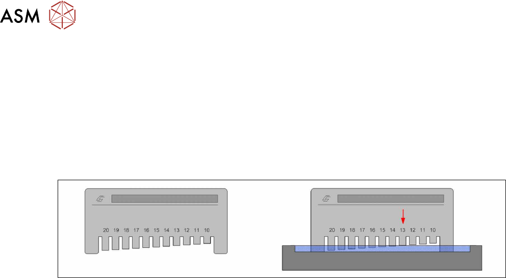
Structure of measuring device
On one side of the rectangular measuring instrument there are engraved teeth with increasing spa-
cing from the contact surface. A scale is marked above the teeth and the engraved numbers indic-
ate the distance from the contact surface in µm. These measuring devices are usually made of
steel so that they can be cleaned with solvents.
Measurement principle
The measuring device is dipped into the layer of flux. The point at which the flux touches a tooth is
the layer thickness measurement (arrow in right-hand image).
Performing the measurement
► Place the measuring device onto the flux surface as shown above and press down to the base
of the cavity.
► Perform a brief "combing" movement while applying moderate pressure.
► Take the measuring device vertically up and out of the flux.
► Determine the shortest tooth which is coated by flux.
► Read the value on the scale at this point.