00198521-01_UM_LDU_E_EN.pdf - 第46页
4 Operation 4.7 Aligning 46 User Manual SIPLACE Linear Dipping Unit E 12/2018 4.7 Aligning You need the following tools to align the LDU: ● Phillips screwdriver ● Allen key 3 mm ● Allen key 10 mm ► Lift off the dip plate…
4 Operation
4.6 Performing a height measurement
User Manual SIPLACE Linear Dipping Unit E 12/2018 45
Definitions
●
Measuring point 1: reference point.
●
Absolute height [µm]: the measured height of the respective measuring point.
●
Relative height [µm]: the deviation of the absolute height of measuring point 2 or 3 to the ab-
solute height of the reference point. This value is always 0 for the reference point.
Preconditions
► The placement machine must be exactly level to the ground.
► The cavity of the dip plate must be free of flux.
► There must be a nozzle on the placement head.
Performing a height measurement
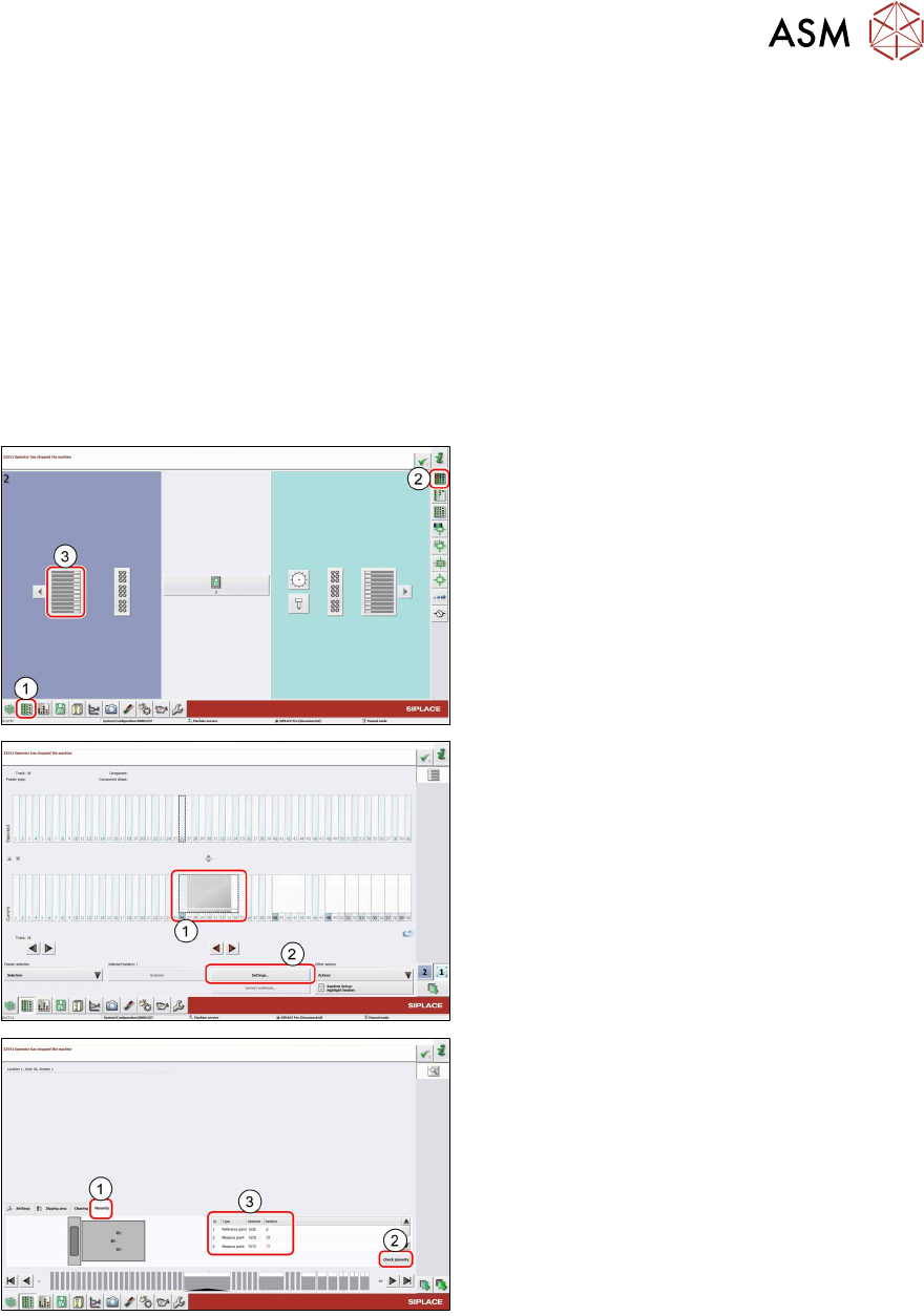
► In the station software, select the Setup
view(1) and then the Locations area (2).
► Select the Table (3) on which the LDU is
set up.
► Select the icon of the LDU(1).
► Click on the Settings... button (2).
► Select the Planarity tab(1).
► Click on the Check planarity button(2).
The machine will perform the measurement and
then show the values determined in the table
(3).
► Read the values.
●
The relative values for measuring points 2 and 3 are lower than +/- 50 μm: the LDU is set
correctly.
●
The relative values for measuring points 2 and 3 are greater than +/- 50 μm:
► Perform the following steps until the relative values for measuring points 2 and 3 are lower
than +/-50µm:
► Align the LDU (see 4.7 "Aligning" [}46]).
► Repeat the height measurement.
4 Operation
4.7 Aligning
46 User Manual SIPLACE Linear Dipping Unit E 12/2018
4.7 Aligning
You need the following tools to align the LDU:
●
Phillips screwdriver
●
Allen key 3 mm
●
Allen key 10 mm
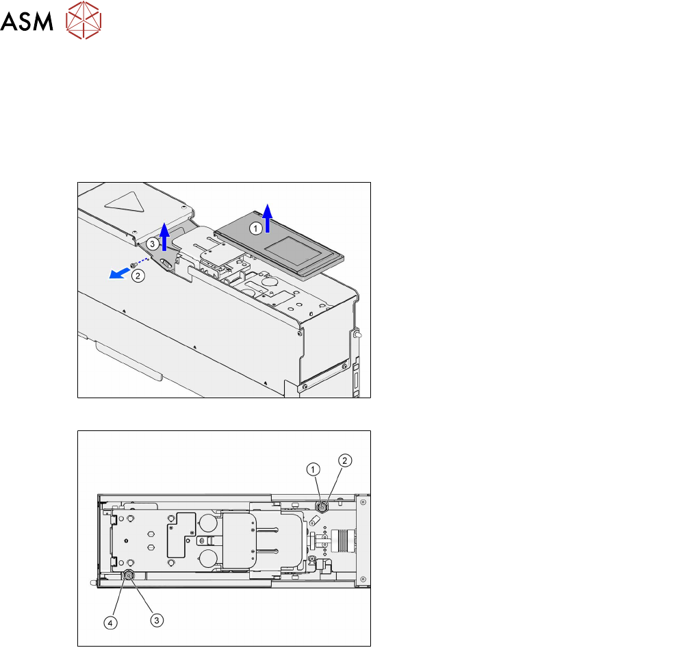
► Lift off the dip plate(1).
► Remove the fastening screw of the coup-
ling cover(2).
► Lift off the coupling cover(3).
The screws for aligning the LDU are easily accessible from above:
1. Rear fixing screw (Allen screw 3mm)
2. Rear adjustment screw (Allen screw
10mm)
3. Front fixing screw (Allen screw 3mm)
4. Front adjustment screw (Allen screw
10mm)
Each of the two pairs consisting of fixing screw and adjustment screw is arranged concentrically.
► Loosen the two fixing screws (1) and (3) with an Allen key of size 3mm.
► Align the dip plate with the two adjustment screws (2) and (4) (Allen key 10 mm).
Rotating one of the adjustments screws clockwise will lift the dip plate at this position.
Rotating one of the adjustment screws counterclockwise will lower the dip plate at this position.
One revolution of the adjustment screws corresponds to lifting or lowering by 0.5mm.
► Tighten the two fixing screws (1) and (3) with a maximum torque of 0.75Nm.
► Fit the coupling cover.
► Fit the dip plate.
4 Operation
4.8 Setting the zero position of the dip plate
User Manual SIPLACE Linear Dipping Unit E 12/2018 47
4.8 Setting the zero position of the dip plate
The dip plate has to be exactly on the same level as the park plate in order to move the squeegee
unhindered and prevent that the flux tank get stuck to the park plate or dip plate. This position of
the dip plate is the zero position.
The zero position is set with the help of the function keys of the LDU control unit.
Preconditions
●
The dip plate must be fitted.
●
The park plate must be fitted.
●
The flux tank must be removed.
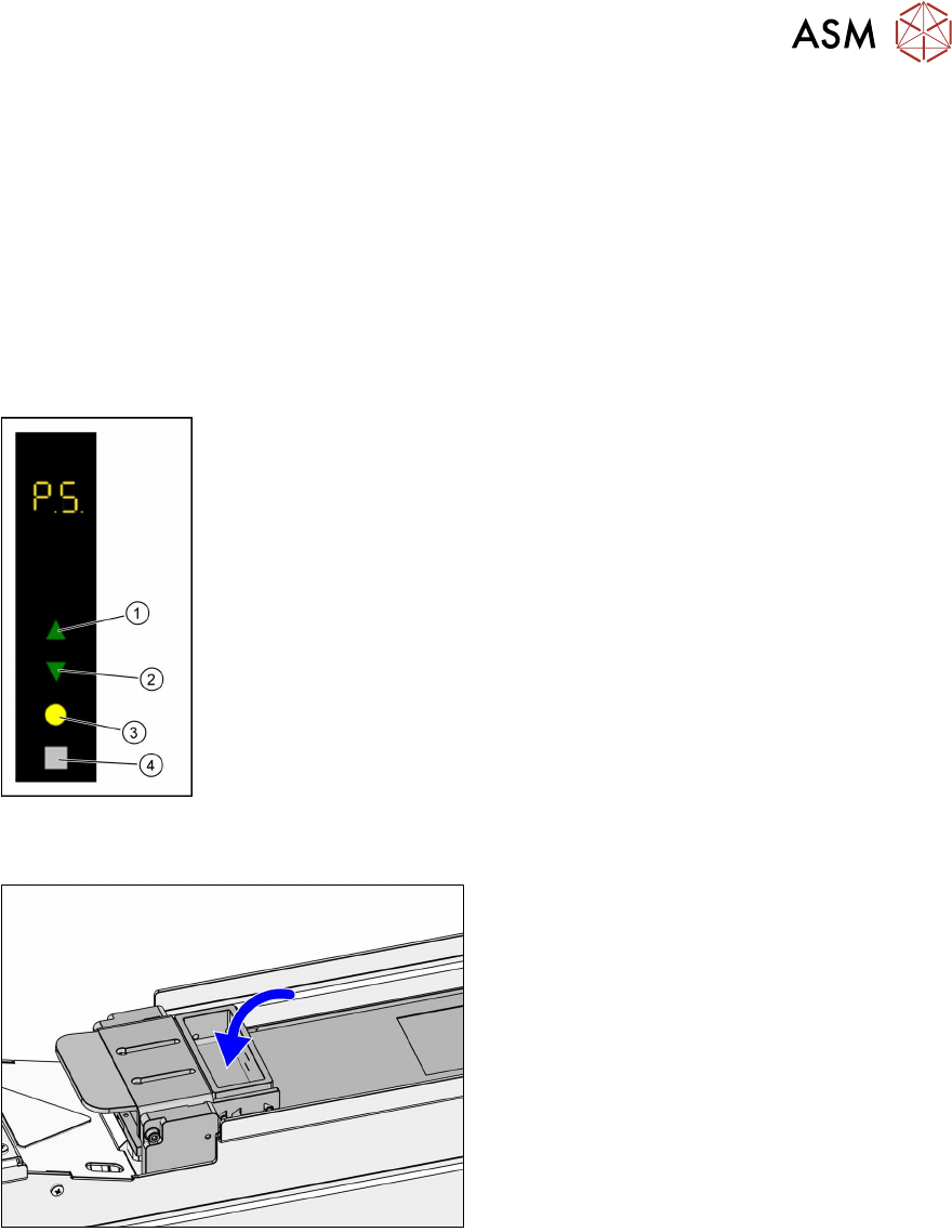
► Use the Up (1) or Down key (2) to select the operating mode P1.
► Press and hold theSelect(3) and Adjust (4) keys simultaneously to
switch to the Service activity level.
► Use the Up (1) or Down key (2) to select the operating mode P5.
► Press the Select button (3) to start the calibration.
► Use the Up (1) and Down keys (2) to move the dip plate until the park
plate and the dip plate are exactly level.
► Press the Select button (3) to save the zero position.
4.9 Filling in flux
► Fill in the flux in the flux tank.