OM-1670-001_w.pdf - 第10页
OM-1670 7 4. Pattern Program 4.1 Nozzle Stk 1, 2 data When the [Nozzle Stk 1] or [Nozzle Stk 2] tab is pressed on the "PL Head/ Nozzle" window, the following tab sheet appears. Note (a) When the nozzle stocker …
OM-1670
6
3. Nozzle Stocker for Multi-Functional Nozzle Setup
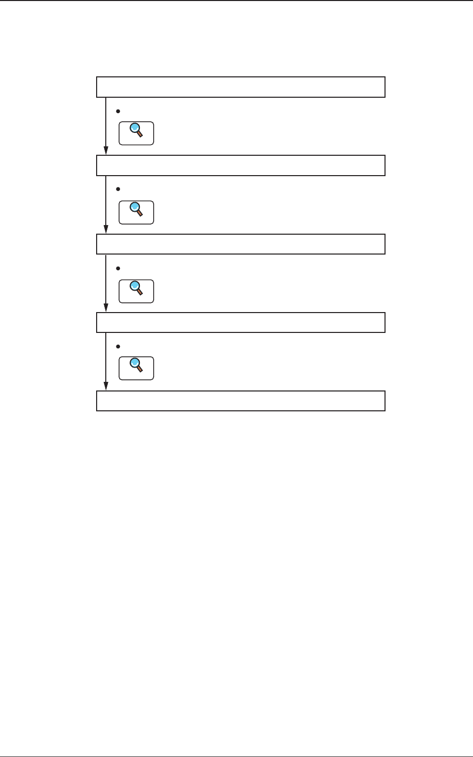
Procedure
Pattern Program Setting
Nozzle Change Setting
Unit Change Setting
Automatic Operation
Unit Adjustment Setting
Set the pattern program.
Refer to "4. Pattern Program" for details.
Refer to "5. "NOZ. CHG." window" for details.
Refer to "6. "Unit Change" window" for details.
Refer to "7. "Unit Adj." Submenu" for details.
Set the nozzle change.
Set the unit change.
Set the unit adjustment.
Reference
Reference
Reference
Reference
Fig. 2
1011-001
3. Nozzle Stocker for Multi-Functional Nozzle Setup Procedure
OM-1670
7
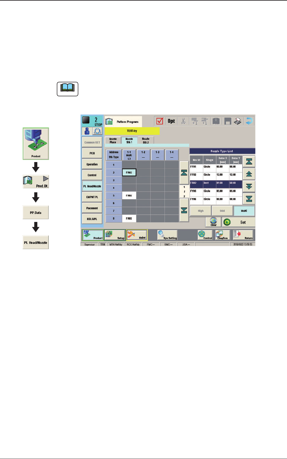
4. Pattern Program
4.1 Nozzle Stk 1, 2 data
When the [Nozzle Stk 1] or [Nozzle Stk 2] tab is pressed on the "PL Head/
Nozzle" window, the following tab sheet appears.
Note
(a) When the nozzle stocker for multi-functional nozzle has been attached onto
the nozzle stocker No. 1 position, this window appears.
(b) The display in the window varies depending on the selected option.
Fig. 3 Condition where the Nozzle Stocker "L3" for
Multi-Functional Nozzles has been attached.
Graphic
Development
1011-001
4. Pattern Program
OM-1670
8
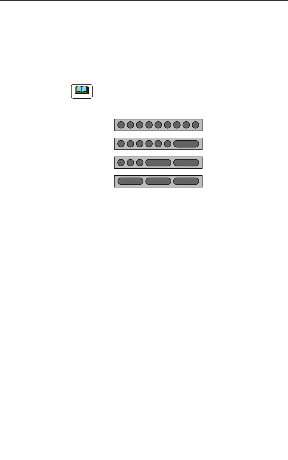
Address Stk Types 1 to 9
Using these parameters, the nozzles are housed in the specied positions
(address stocker type) in the nozzle stocker.
Multi
: 1 to 9
Multi L1
: 2,
4 to 9
Multi L2
: 2, 5, 7 to 9
Multi L3
: 2, 5, 8
Note
Because large nozzles are housed in L1, L2 and L3 stockers for multi-
functional nozzle, any addresses except for the selectable addresses, are
not used.
123456789
2456789
25789
258
Standard
L1
L2
L3
Fig. 4
1011-001
4. Pattern Program