4OM-1075-002.pdf - 第280页
4.3.2 Component Recognition Errors AA BB C DDD EE Detail Code : Kinds of Errors (00 to 99) Detail Code : Kinds of Errors (000 to 999) Secondary Error Classification: Error Classification (1 to 99) Primary Error Classific…
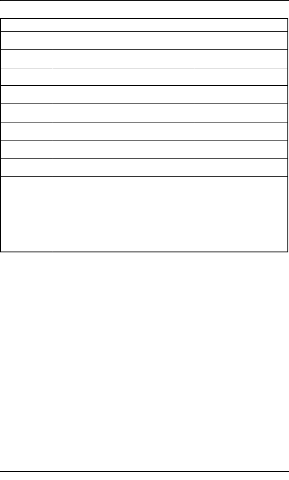
Error ID Item Description
01 63 2 00000 The specified error image is not saved. -----
01 64 1 00000 A-E Data is incorrect -----
01 65 1 00000 Device Code or Type Code is incorrect -----
01 66 1 00000 Initialization mode is incorrect -----
01 90 0 00000 Recognition Communication Procedure Error -----
01 91 0 00000 Recognition Communication Error -----
01 92 0 00000 Recognition Communication Error -----
01 93 0 00000 Recognition Communication Error -----
(Cause 1) Self-Diagnostics Error Message
(Remedy 1) Contact our service personnel for details.
4.3 Recognition Error IDs and Remedial Procedures
0308-001 2-139-3 AHB01ETRP
4.3.2 Component Recognition Errors
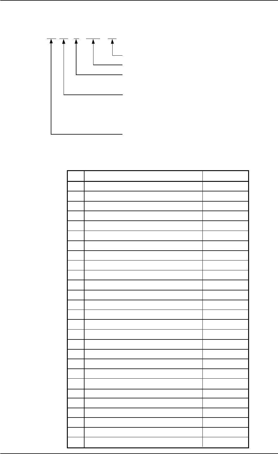
AA BB C DDD EE
Detail Code : Kinds of Errors (00 to 99)
Detail Code : Kinds of Errors (000 to 999)
Secondary Error Classification:
Error Classification (1 to 99)
Primary Error Classification:
Recognition Algorithm (00 to
99)
Refer to Table 4B10.
Classification of Recognition Functions (02)
Error Classification: Recognition Algorithm
Table 4B10
BB Recognition Algorithm Remarks
00 Others
01 Edge (Rectangle) Front Lighting
02 Corner Back Lighting
03 Corner Front Lighting
04 Edge (General Purpose) Back Lighting
05 Edge (General Purpose) Front Lighting
06 Center of Gravity (Angle Detected) Back Lighting
07 Center of Gravity (Angle Detected) Front Lighting
08 Center of Gravity (Angle Not Detected) Back Lighting
09 Center of Gravity (Angle Not Detected) Front Lighting
10 Line Back Lighting
11 Line Front Lighting
31 Leaded Back Lighting
32 Leaded Front Lighting
33 Multiple Pin Leads (Standard) Back Lighting
34 Multiple Pin Leads (Standard) Front Lighting
35 Multiple Pin Leads (General Purpose) Back Lighting
36 Multiple Pin Leads (General Purpose) Front Lighting
37 Lead (Special) Back Lighting
38 Lead (Special) Front Lighting
39 Lead (Standard 2) Front Lighting
40 Multi-Pin Lead (Standard 2) Back Lighting
41 Multi-Pin Lead (Standard 2) Front Lighting
91 Grid Pattern Front Lighting
92 Grid Pattern Front Lighting
93 Grid Pattern (Divided) Front Lighting
94 Grid Pattern (Divided) Front Lighting
4.3 Recognition Error IDs and Remedial Procedures
0206-002 2-140 AHB01ETRP
(a) Error IDs "*" will be filled with primary error classification
and detail codes.
(b) When an error ID other than the described ones is issued,
contact our service personnel for some advice.
Table 4B11
Error ID Item Description
02 ** 1000 ** Component Missing Component was not found.
(Cause 1) The feeders may be loaded with components different from the specified ones.
(Cause 2) The vacuum suction force is too weak.
(Cause 3) An improper nozzle is selected for the components or vice versa.
(Remedy 1) Check if proper components are used.
(Remedy 2) Check the vacuum pressure.
(Remedy 3) Check the parameters in the nozzle type data and the component library
data.
02 ** 2101 ** Error in Outward Length Inspection Cmponent Outward Length X is incorrect.
02 ** 2102 ** Error in Outward Length Inspection Component Outward Length X is shorter than the
tolerance.
02 ** 2103 ** Error in Outward Length Inspection Component Outward Length X is longer than the
tolerance.
02 ** 2104 ** Error in Outward Length Inspection Component Outward Length Y is incorrect.
02 ** 2105 ** Error in Outward Length Inspection Component Outward Length Y is shorter than the
tolerance.
02 ** 2106 ** Error in Outward Length Inspection Component Outward Length Y is longer than the
tolerance.
02 ** 2107 ** Error in Outward Length Inspection Component Outward Length X or Y is incorrect.
02 ** 2108 ** Error in Outward Length Inspection Component Outward Length X or Y is shorter than
the tolerance.
02 ** 2109 ** Error in Outward Length Inspection Component Outward Length X or Y is longer than
the tolerance.
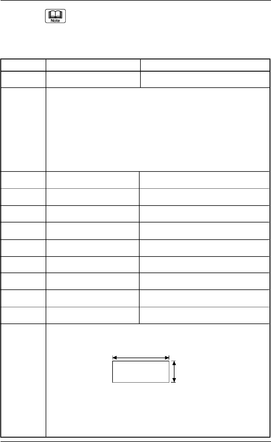
(Cause 1) Wrong parameters are set in the "X [mm]" and "Y [mm]" text boxes of "Mold
size" and the "Mold size tolerance X [mm]" and "Mold size tolerance Y [mm]"
text boxes for the selected components.
(Remedy 1) Check the selected components and the parameters set in the "X [mm]"
and "Y [mm]" text boxes of "Mold size" and the "Mold size tolerance X
[mm]" and "Mold size tolerance Y [mm]" text boxes for the selected com-
ponents in the component library data.
Correct wrong parameters if they are set in the component library data.
0206-002 2-141 AHB01ETRP
X
Y
Fig. 4B50
4.3 Recognition Error IDs and Remedial Procedures