4OM-1075-002.pdf - 第94页
3. 1 T ypical Description T able 4B4 Error ID Item Description 050301 Y2 Axis Data The driver data was detected outside of the possible range. (Cause 1) Self-Diagnostics Error Message (Remedy 1) Zero all axes and re-star…
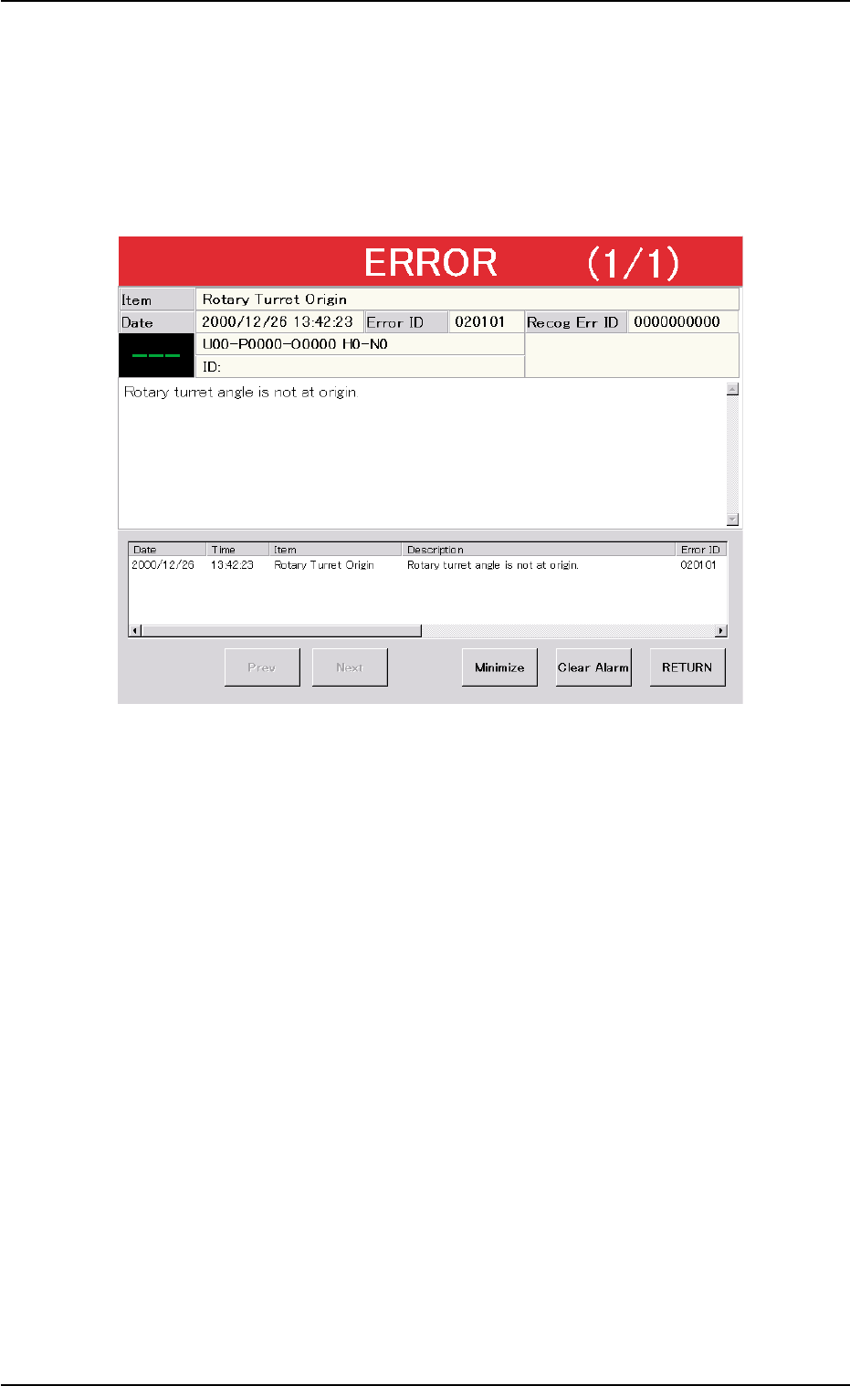
3. Troubleshooting after "ERROR" Window (Error ID)
Assuming "Error ID", "Item (Error Name)", and "Description" in the "ER-
ROR" window as an index, the system retrieves the related page of the
instruction manual.
Refer to "3.1 Typical Description" for the detailed description.
Fig. 4B15 Example of "ERROR" Window
3. Troubleshooting after "ERROR" Window (Error ID)
0206-002 2-9 AHB01ETRP
3.1 Typical Description
Table 4B4
Error ID Item Description
050301 Y2 Axis Data The driver data was detected outside of the possible
range.
(Cause 1) Self-Diagnostics Error Message
(Remedy 1) Zero all axes and re-start the operation.
When the machine cannot be set to its normal condition, consult our service
personnel for the remedy.
050401 Y2 Axis Limit (+) Limit error has been detected.
050402 Y2 Axis Limit (-) Limit error has been detected.
(Cause 1) The X1 axis might have overrun due to generation of noises, overcurrent, etc.
The sensor may be defective.
(Remedy 1) Zero all axes and re-start the operation.
When the machine cannot be set to its normal condition, consult our service
personnel for the remedy.
(Continued to the next page)
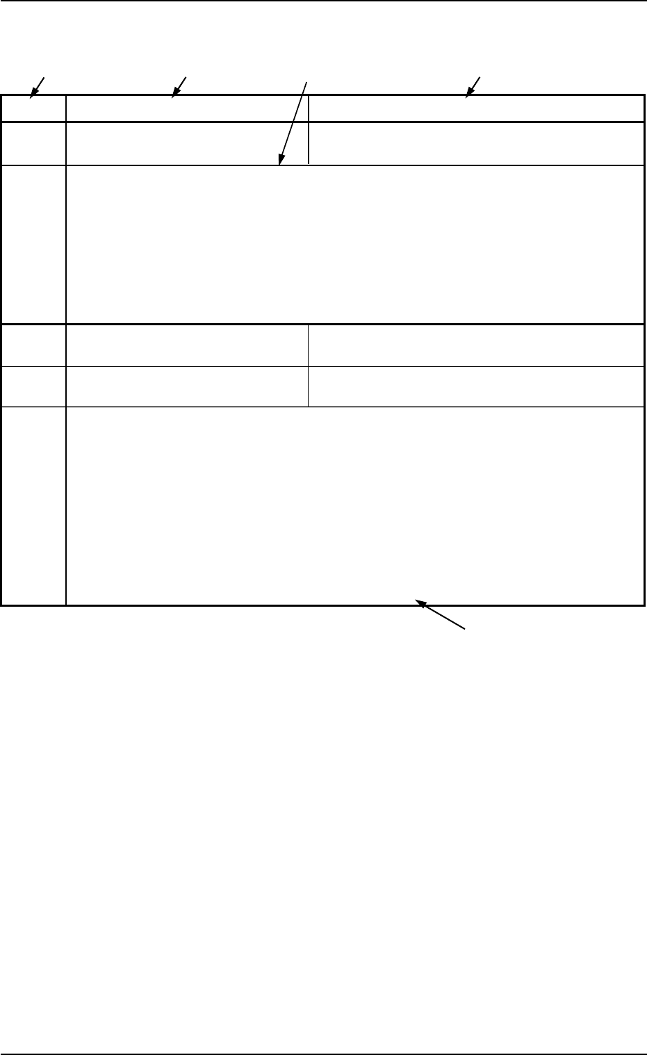
*1 The error IDs (IDs displayed in the "ERROR" window) are described
in the numerical order.
*2 Described are the error name (item) and the description in the "ER-
ROR" window.
*3 Described are the causes and remedial procedures of the errors
(Item and Description).
The causes and remedies are correlated as follows.
(Cause 1)
ÆÆ
ÆÆ
Æ (Remedy 1)
(Cause 2)
ÆÆ
ÆÆ
Æ (Remedy 2)
(Cause 3)
ÆÆ
ÆÆ
Æ (Remedy 3)
*4 This indicates that the related contents are described subsequently
on the next page.
*4
*2
*3
*2
*1
3.1 Typical Description
0107-001 2-10 AHB01ETRP
3.2 Error IDs and Controlled Areas
0308-004 2-1 1 AHB01ETRP
3.2 Error IDs and Controlled Areas
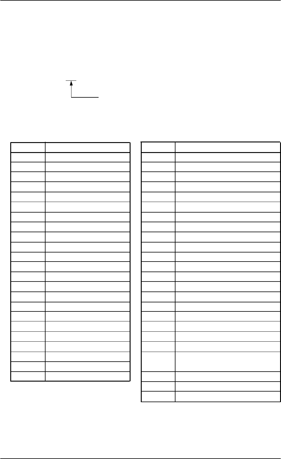
Basic System of Error IDs
An error ID is expressed by 6 digits (decimal number) as follows.
Major Classification of "Operation Axis", "Process
Error", and "Teaching Operation"
Error IDs and Controlled Areas
Table 4B5
Error ID Operation Axis Error ID Process Error
02 X1 Axis 60 Safety Device
03 X2 Axis 61 Data
04 Y1 Axis 63 Self-Diagnostics
05 Y2 Axis 65 Recognition Communication
06 L1 Axis 66 P.E.C. Recognition
07 L2 Axis 67 Component Recognition
08 Z1 Axis 68 Pickup Error
09 Z2 Axis 69 Nozzle Change
0a NC1 Axis 6a Unit P.C.B. Error
0b NC2 Axis 6b Lead Coplanarity Detection
0c BPC Axis 6c Others
0d PWC Axis 6d Automatic Teaching
0e CNVL Axis 6f Multi-Layer Tray (L)
0f CNVP Axis 70 Multi-Layer Tray (R)
10 CNVR Axis 71 Bank Carriage Cart A
11 Traverse 1 72 Bank Carriage Cart B
12 Traverse 2 75 Input Conveyor
13 Elevator 1 76 Locate Conveyor
14 Elevator 2 77 Output Conveyor
20 Feeder Base #1 78 Component Output Conveyor
21 Feeder Base #2 79 Component Recognition Test,
22 Feeder Base #3 Hysteresis Test
23 Feeder Base #4 7a Program Error
fe System Error
ff Interlock Interrupt