Nordson_EFD_P-Jet_SolderPlus_Operating_Manual.pdf - 第18页
Liquidyn P-Jet SolderPlus Jet Valve 18 www.nordsonefd.com info@nordsonefd.com +1-401-431-7000 Sales and service of Nordson EFD dispensing systems are available worldwide. 8. • Using a wooden pick, apply a small amount of…
Liquidyn P-Jet SolderPlus Jet Valve
17www.nordsonefd.com info@nordsonefd.com +1-401-431-7000 Sales and service of Nordson EFD dispensing systems are available worldwide.
Change the Fluid Body or Tappet (Optional) (continued)
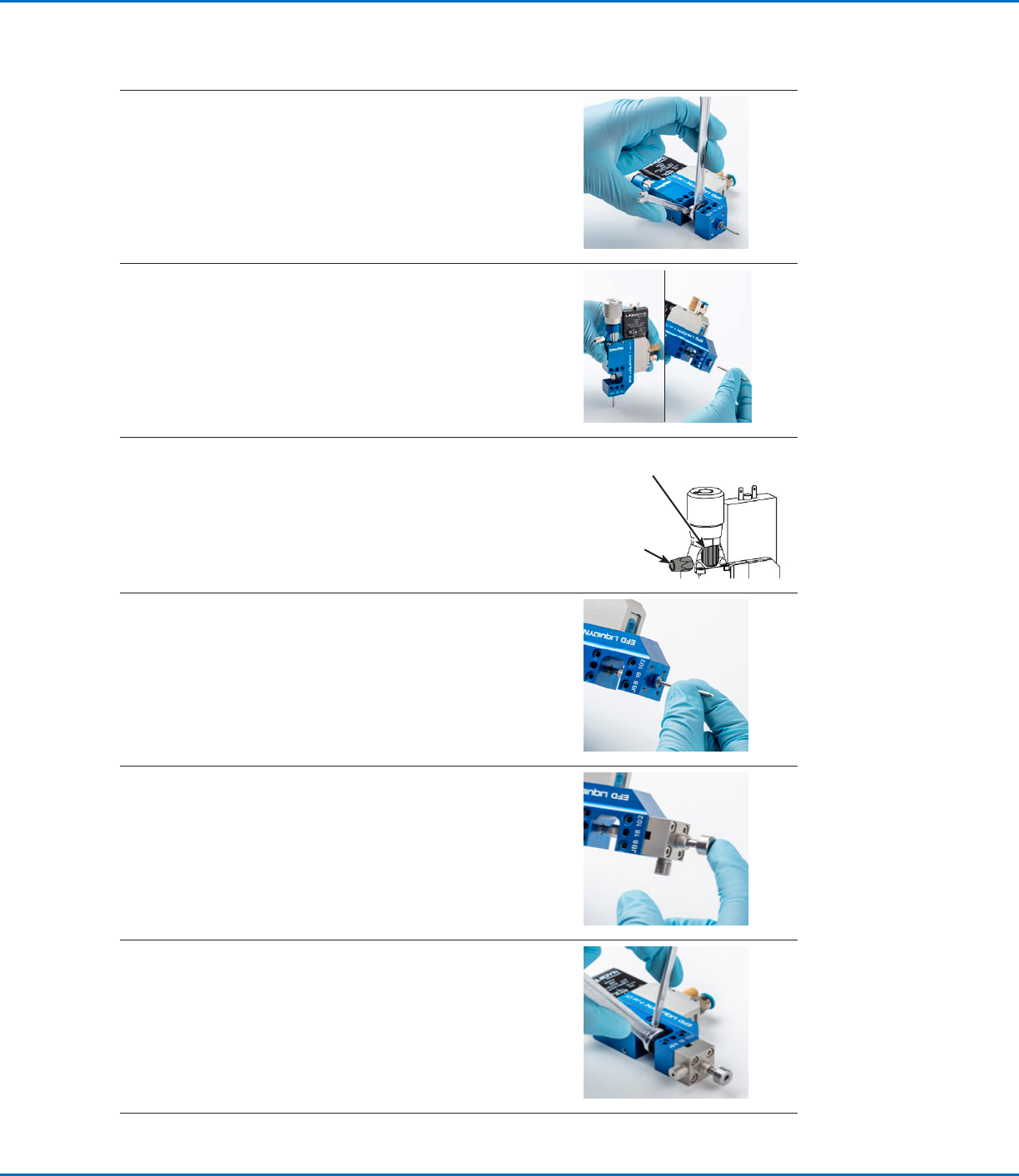
2. • Loosen the tappet nut with a wrench (6 mm to loosen the
tappet nut; 3.5 mm to hold the tappet rod steady).
3. • Press in the tappet with controlled pressure until the
clamping sleeve between the tappet and nut loosens. A
piece of wood or hard rubber is suitable to press against.
• Remove the tappet.
4. Turn the force screw fully counterclockwise as follows (to
eliminate any spring force on the tappet):
• Completely loosen the raster element.
• Turn the force screw counterclockwise until it stops.
• Completely tighten the raster element to secure the force
screw.
Force
screw
Raster
element
5. • Insert the replacement tappet until the tappet stops.
6. • Insert the tappet alignment tool into the fluid body and
around the tappet; push the tool in until it is firmly held in
place by its tapered sides.
7. • Using the same technique described in step 2, tighten
the tappet nut (while the tappet alignment tool is still
installed).
Torque: 0.1 N•m (0.7 ft-lb) maximum
• Remove the tappet alignment tool from the fluid body.
Continued on next page
Liquidyn P-Jet SolderPlus Jet Valve
18 www.nordsonefd.com info@nordsonefd.com +1-401-431-7000 Sales and service of Nordson EFD dispensing systems are available worldwide.
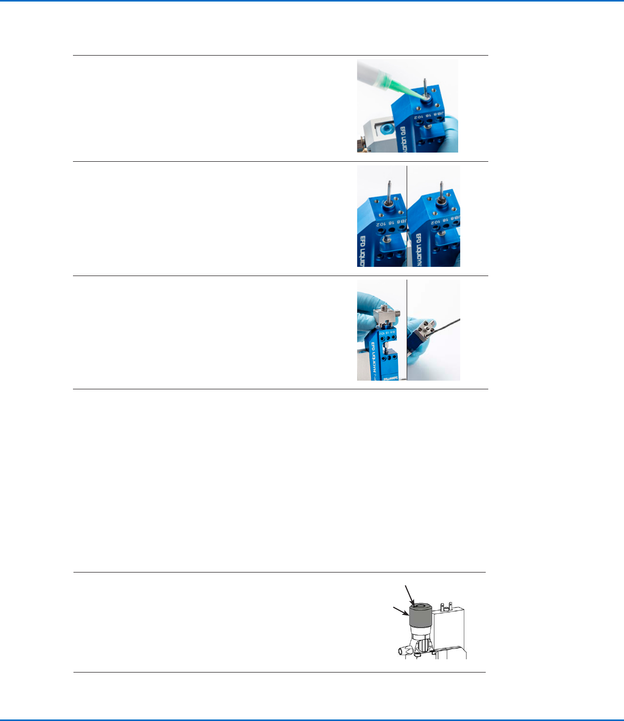
8. • Using a wooden pick, apply a small amount of barrier
grease at the base of the replacement tappet and
distribute this around the annulus.
9. • Install a new O-ring (standard material: NBR) on the
tappet and press the O-ring down into the greased
annulus.
• Distribute the grease evenly so that the entire sealing
surface of the O-ring is covered.
• Install the second (grease-free) O-ring on the tappet on
top of the initial O-ring.
10. • Mount the initial or replacement fluid body precisely over
the tappet without tilting it. Tighten the screws crosswise.
Torque: 0.8 N•m (5.9 ft-lb) maximum
11. • Continue to the next procedure to set the tappet
concentricity.
Change the Fluid Body or Tappet (Optional) (continued)
Set the Tappet Concentricity
Follow this procedure to set the tappet concentricity (common center) as follows:
• Anytime the tappet is changed or replaced.
• Whenever the dispensing performance deteriorates.
You will need the following items:
• Concentricty tool
• Nozzle retaining nut
Refer to “Tools and Supplies” on page41 for component part numbers.
1. Turn the stroke adjustment knob fully counterclockwise as
follows (so that it is not forcing the tappet into a forward
position):
• Use a hex wrench to loosen the locking set screw.
• Turn the stroke adjustment knob counterclockwise until it
stops.
• Tighten the locking set screw to secure the knob.
Locking set screw
Stroke
adjustment
knob
Continued on next page
Liquidyn P-Jet SolderPlus Jet Valve
19www.nordsonefd.com info@nordsonefd.com +1-401-431-7000 Sales and service of Nordson EFD dispensing systems are available worldwide.
2. If you have not already done so, turn the force screw fully
counterclockwise as follows (to eliminate any spring force
on the tappet):
• Completely loosen the raster element.
• Turn the force screw counterclockwise until it stops.
• Completely tighten the raster element to secure the force
screw.
Force
screw
Raster
element
3. • Remove the nozzle, if present.
• Install the concentricity tool onto the fluid body where the
nozzle would mount.
• Install the nozzle retaining nut to secure the concentricity
tool.
4. • Turn the force screw one (1) click counterclockwise so
that there is a low spring force pushing the tappet onto
the concentricity tool.
Force
screw
Raster
element
5. • Place the valve upright under a measuring system (such
as a digital microscope with measurement capability).
• Adjust the magnification to 100 times (100x) and focus on
the flat surface of the tappet, which is at the same height
as the concentricity tool.
Tappet
Concentricity
tool
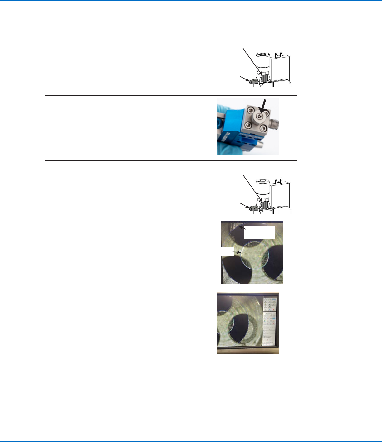
6. • Use the measuring system’s center-to-center tool to
measure the concentricity of the tappet to the inside ring
of the concentricity tool.
NOTE: The three holes in the concentricity tool act as
windows to view the inner diameter.
7. • Repeat the concentricity measurement three times
by repeating steps 1–6 (including turning the stroke
adjustment knob back when removing / installing the
concentricity tool).
• Average all three measurements. An acceptable tappet
concentricity is <75 µm.
Set the Tappet Concentricity (continued)