Nordson_EFD_P-Jet_SolderPlus_Operating_Manual.pdf - 第44页
Liquidyn P-Jet SolderPlus Jet Valve 44 www.nordsonefd.com info@nordsonefd.com +1-401-431-7000 Sales and service of Nordson EFD dispensing systems are available worldwide. Appendix B, P-Jet SolderPlus V alve Interface Ove…

Liquidyn P-Jet SolderPlus Jet Valve
43www.nordsonefd.com info@nordsonefd.com +1-401-431-7000 Sales and service of Nordson EFD dispensing systems are available worldwide.
Appendix A, About Non-Contact Dispensing
The way a micro-dispensing valve system works for the non-contact dispensing of micro-deposits of fluid is
comparable to the way an ink-jet system works. In both systems, a jetted deposit with a spherical head and a thin
thread (shaped much like a tadpole) is formed. The dimensions vary depending on the material being dispensed, the
process, and the valve settings.
As the deposit is squeezed (or jetted) out of the nozzle opening, the thin thread constricts because of the absence
of further fluid supply, the surface tension, and also the continual movement of the deposit, until the deposit finally
separates from the nozzle opening. The thread extending from the deposit’s spherical head is either absorbed by
the head or separated into at least one more (sometimes many more) smaller head. This depends on the rheological
properties of the fluid. At low airflows or in asymmetrical drop-off conditions, a smaller head can land on the
substrate next to the main head, creating satellite drops. The thin thread formed at the nozzle output retracts back
into the nozzle due to the surface tension and remains at the nozzle output. This residue at the nozzle output can
have a negative influence on the dispensing properties of the valve.
The formation of satellite drops and / or nozzle contamination can be reduced or eliminated by using the correct
dispensing settings.
Low Viscosity Materials
Try the following to reduce or eliminate the formation of satellite drops: Reduce the pressure supplied to the material
by reducing both the fluid pressure and the operating pressure and also by loosening the force screw. Refer to
“Adjusting the Force Screw” on page28.
NOTE: With low viscosity materials, nozzle contamination is usually a minor issue because the subsequent drop
removes the residue at the nozzle output.
High Viscosity Materials
With high viscosity materials, the thin thread that retracts back into the nozzle and the resulting nozzle
contamination can negatively affect the dispensing process. Try the following to reduce or eliminate nozzle
contamination:
• Increase the amount of supplied force. The amount of force depends on the operating pressure and the
pretension of the valve tappet. Increasing the amount of force can have a positive effect on the drop-off
properties of the deposit and thus improve process reliability. Refer to “Adjusting the Force Screw” on
page28.
• Warm the material being dispensed to reduce the viscosity. This is particularly effective for highly viscous
materials. In most cases, the dispensing process reliability of highly viscous materials improves with decreased
viscosity. Material warming can be accomplished by installing a nozzle heater. Refer to “Install a Nozzle Heater
(Optional)” on page20.
NOTE: In general, viscosity halves per 10 Kelvin temperature unit increase. Exceptions are silicone oils and greases,
although elevating the temperature of these materials can lead to improvement.
Deposit Size
The dispensed volume of a deposit depends on the following parameters:
• Cross section of the valve
• Operating pressure
• Fluid pressure
• Position of the stroke adjustment screw or the force screw.
The smallest possible deposit size is subject to physical limitations. The smaller the deposit, the higher the surface
tension in relation to its mass. Thus, the amount of required energy needed for the launch of a deposit raises
significantly in relation to its mass. At a certain point, it is physically impossible to transfer the required energy to the
dispensed material any longer, particularly in the dispensing of highly viscous materials.
Liquidyn P-Jet SolderPlus Jet Valve
44 www.nordsonefd.com info@nordsonefd.com +1-401-431-7000 Sales and service of Nordson EFD dispensing systems are available worldwide.
Appendix B, P-Jet SolderPlus Valve Interface Overview
The Liquidyn P-Jet SolderPlus pneumatic micro-dispensing jet valve system is designed for the non-contact
dispensing of EFD SolderPlus solder paste. The valve can be operated using a Nordson EFD Liquidyn valve
controller or directly by the customer via a 24V input using a customer-supplied controller or a programmable logic
controller (PLC).
Electrical Control
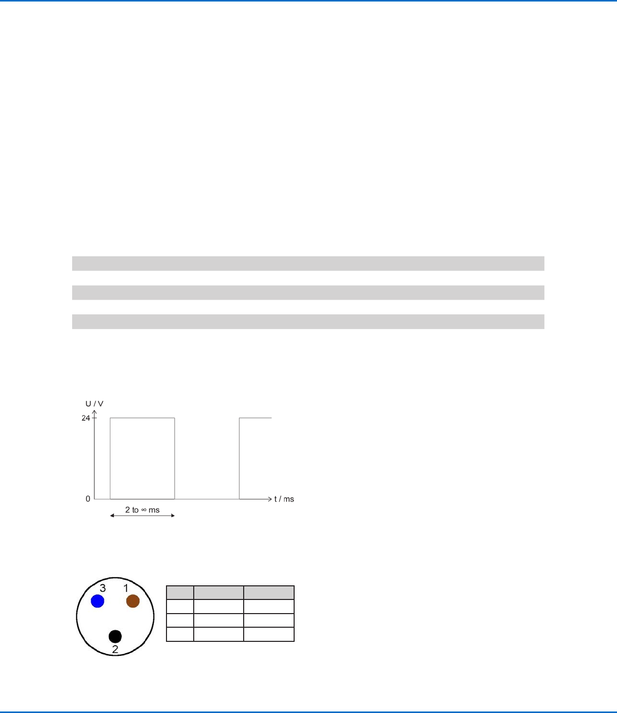
The valve is triggered by a square-wave signal (24 VDC). The length of the pulse from the control signal defines the
opening time of the valve and can be set from 2 ms to infinity. Most PLC systems make use of high performance
transistor outputs which are suitable to control the valve directly. The valve is electrically connected to the control
system via the supplied M8 valve cable.
NOTE: To continuously dispense the exact amount with every shot, the Pulse Time must be kept constant. Observe
the cycle time of the PLC; if necessary, check the signal with an oscilloscope.
Electrical Specifications
Item Specification
Maximum operating frequency 100Hz
Pulse Time Starting at 2 ms
Input voltage 24 VDC, PLC compatible
Power consumption 0.5 Amp (peak 5.0 Amp)
M8 Valve Cable Pin Positions
Pin Color Function
1 Brown None
2 Black Valve (+)
3 Blue Valve (-)
Oscillogram (Valve Output) for a Liquidyn P-Jet SolderPlus Valve
Liquidyn P-Jet SolderPlus Jet Valve
45www.nordsonefd.com info@nordsonefd.com +1-401-431-7000 Sales and service of Nordson EFD dispensing systems are available worldwide.
Optional Nozzle Heater Control
A nozzle heater can be installed on the valve in place of the retaining nut. The heater can be controlled using a
separate temperature controller (such as the Liquidyn T10) or by the Liquidyn V200 controller.
To use another method for controlling the heater, the following information applies:
• The heater comprises a heating coil and a 100-ohm platinum (PT100) resistance temperature detector (RTD).
• The heater can be triggered by most control units.
• Heater power consumption is approximately 1.3 Amps, with 24 VDC used during the heating process.
NOTE: The maximum heater temperature is 90° C (194° F). For consistent dispensing results, keep the control
deviation to a minimum (lower than 3%).
Nozzle Heater Specifications
Item Specification
Input voltage 24 VDC
Maximum power consumption 1.3 Amp
Maximum nozzle heater temperature 90° C (194° F)
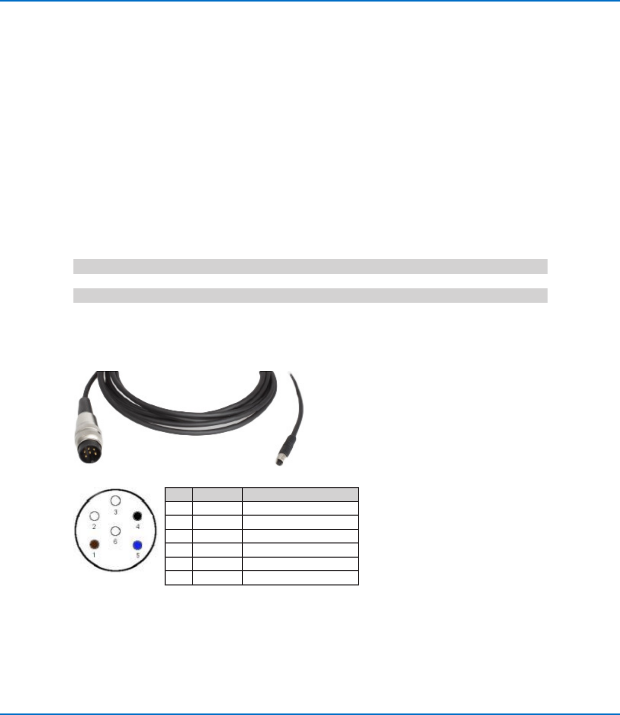
Nozzle Heater Cable Pin Positions
Pin Color Function
1 Brown Heating coil
2 White Heating coil
3 White Not assigned
4 Black PT100 RTD
5 Blue PT100 RTD
6 White Not assigned
6-pin plug
M5 plug
Appendix B, P-Jet SolderPlus Valve Interface Overview
(continued)