Nordson_EFD_P-Jet_SolderPlus_Operating_Manual.pdf - 第33页
Liquidyn P-Jet SolderPlus Jet Valve 33 www.nordsonefd.com info@nordsonefd.com +1-401-431-7000 Sales and service of Nordson EFD dispensing systems are available worldwide. 2. • Use the pipe cleaners from the cleaning kit …
Liquidyn P-Jet SolderPlus Jet Valve
32 www.nordsonefd.com info@nordsonefd.com +1-401-431-7000 Sales and service of Nordson EFD dispensing systems are available worldwide.
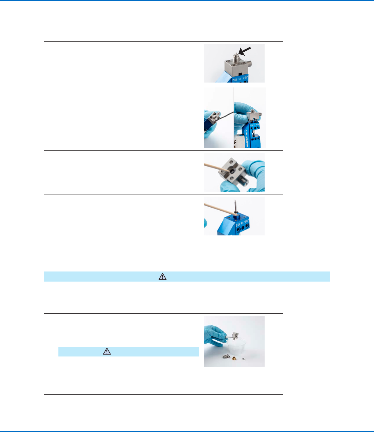
4. • Remove the nozzle from the fluid body.
5. • Unscrew and remove the four screws that secure the
fluid body.
• Carefully remove the fluid body without damaging the
tappet.
6. • Use a toothpick to remove the O-ring from the fluid
body.
7. • Remove the second O-ring from the tappet.
• Clean the tappet and annulus with lint-free paper.
Service (continued)
Disassemble the Valve (continued)
Clean the Valve Components
CAUTION
Never use solvents or cleaning agents that contain halogenated hydrocarbons (such as trichloroethane, methyl
chloride, or dichloromethane). Halogenated hydrocarbons can dissociate, causing an explosion upon contact with
aluminum and galvanized surfaces. Before using a solvent or cleaning agent, check its ingredients.
1. • Submerge all the components in a container filled with
cleaning fluid.
• After 3–5 minutes, remove the components from the
container and clean them with a lint-free cloth.
CAUTION
Do not damage the holes on the sealing faces of the
material carrying components.
• Optional: Use an ultrasonic bath to clean the
components.
Continued on next page
Liquidyn P-Jet SolderPlus Jet Valve
33www.nordsonefd.com info@nordsonefd.com +1-401-431-7000 Sales and service of Nordson EFD dispensing systems are available worldwide.
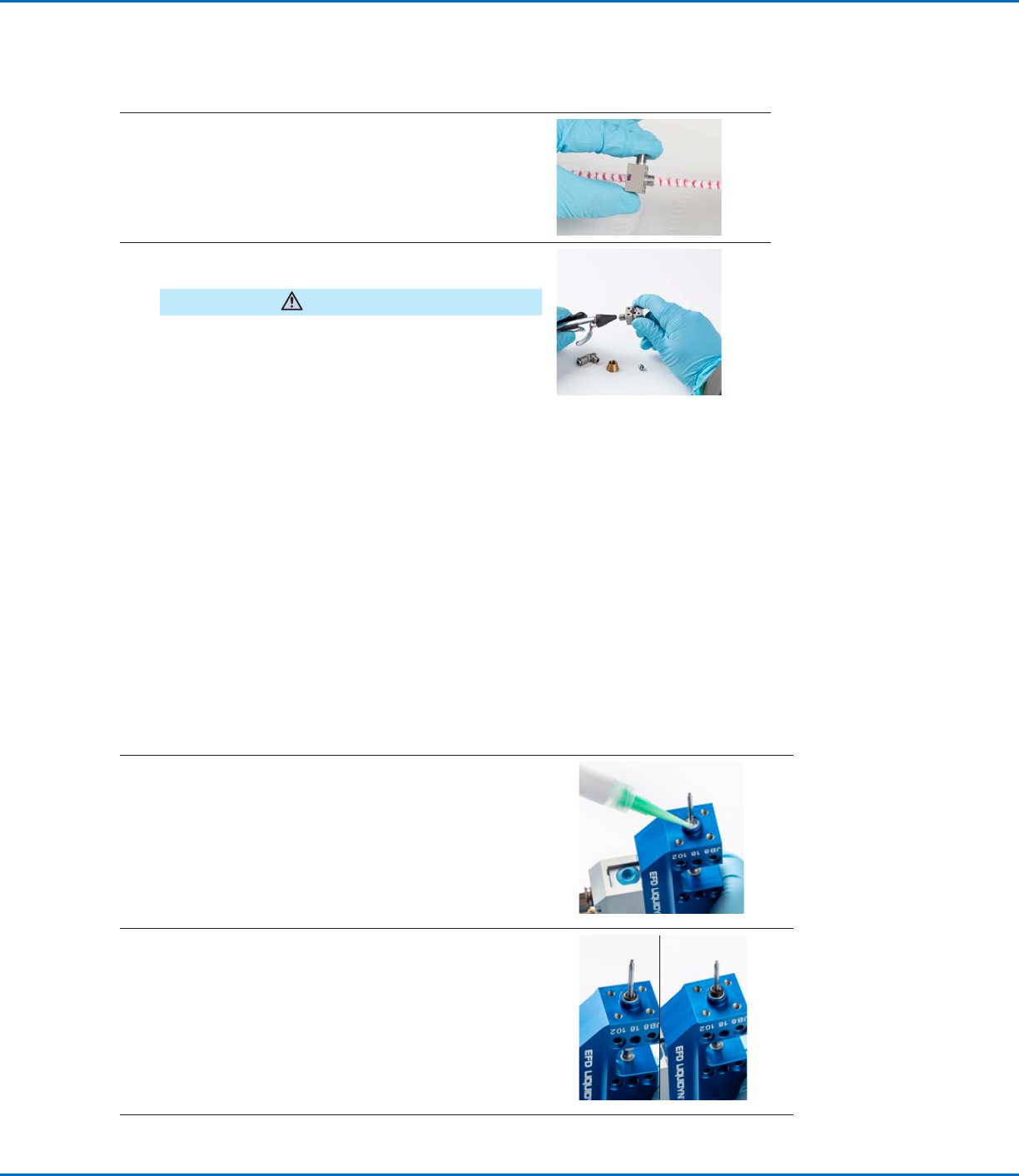
2. • Use the pipe cleaners from the cleaning kit to clean
the disassembled components (luer lock adapter,
nozzle retaining nut, nozzle, fluid body, and the tappet
if needed).
3. • Use compressed air to clear any remaining cleaning
fluid from the parts.
CAUTION
Do not damage the holes on the sealing faces of the
material carrying components.
• Examine the cleaned components for any remaining
residue (especially the nozzle, which should be
examined under a microscope).
• If the parts are still contaminated, repeat the cleaning
process.
Service (continued)
Clean the Valve Components (continued)
Assemble the Valve (After Cleaning)
Follow this procedure to assemble a valve after cleaning it. You will need the following items:
• Hex wrench, size 10
• Hex wrench, size 2.5
• Nozzle
• Nozzle retaining nut
• O-rings and barrier grease
• Wooden pick
• Optional: Heater key (if installing a nozzle heater)
NOTE: The steps provided in this manual are based on a valve with a syringe barrel.
1. • Using a wooden pick, apply a small amount of barrier
grease at the base of the tappet and distribute this around
the annulus.
NOTE: When dispensing instant adhesive
(cyanoacrylates), Nordson EFD recommends petroleum
jelly for use as the barrier grease. Contact Nordson EFD
for assistance in dispensing cyanoacrylates.
2. • Install a new O-ring (standard material: NBR) on the
tappet and press the O-ring down into the greased
annulus.
• Distribute the grease evenly so that the entire sealing
surface of the O-ring is covered.
• Install the second new (grease-free) O-ring on the tappet
on top of the initial O-ring.
Continued on next page
Liquidyn P-Jet SolderPlus Jet Valve
34 www.nordsonefd.com info@nordsonefd.com +1-401-431-7000 Sales and service of Nordson EFD dispensing systems are available worldwide.
Service (continued)
Assemble the Valve (After Cleaning) (continued)
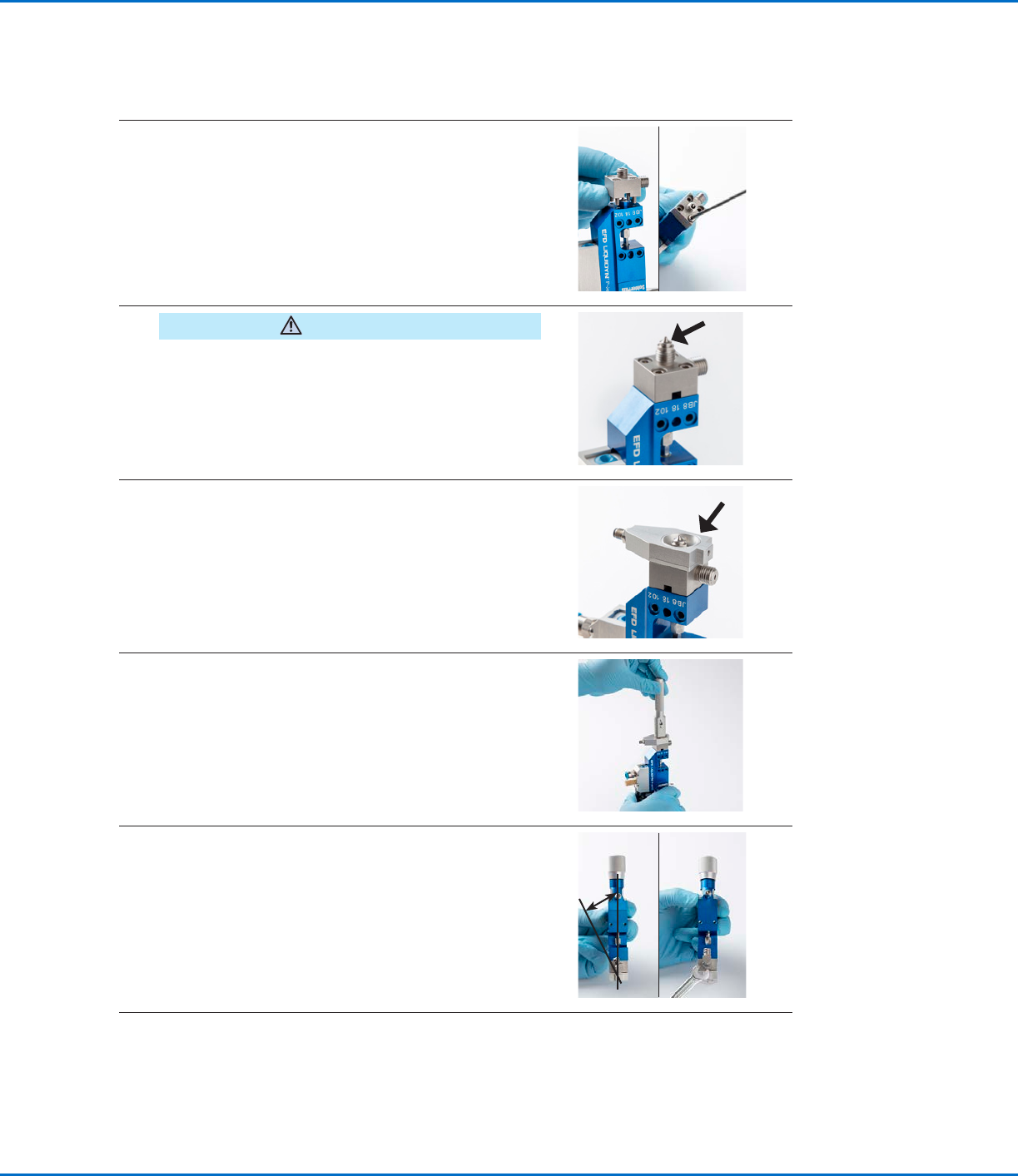
3. • Mount the fluid body precisely over the tappet without
tilting it. Tighten the screws crosswise.
Torque: 0.8 N•m (5.9 ft-lb) maximum
• Optional: To use a different tappet, go to “Change the
Fluid Body or Tappet (Optional)” on page16. Return
here to continue.
4.
CAUTION
If using the P-Jet SolderPlus valve in a solder paste
dispensing application, refer to “Appendix C, Special
Instructions for Solder Paste Dispensing” on page47
for steps that apply only to solder paste dispensing.
• Install the nozzle.
5. • Recommended: Install a nozzle heater.
NOTE: The nozzle heater is an optional component;
however, it is included as a step in this manual because
most solder applications require a nozzle heater.
NOTE: The nozzle is only minimally secured by a nozzle
heater. The nozzle is fully secured by the retaining nut.
6. • Position the nozzle retaining nut in the nozzle heater and
then use the heater key to tighten the nozzle retaining nut.
7. • By hand, thread the luer lock adapter loosely onto the
fluid body, positioning it at a 15° angle from its end
position.
• Tighten the nut with a wrench so that the adapter is
parallel to the straight axis of the valve.
Torque: 5 N•m (3.7 ft-lb) maximum
~15°
Continued on next page